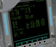
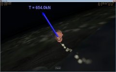
The second shows just residuals, the thrust should be already less than 5% at this point.
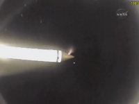
OK. So any idea on why our SRBs starts spinning thanks to the BSMs? Are the positions and angles off?
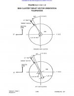
If someone could translate this for me into GMAX usable terms, I could verify the positions and angles:
"eparation motors shall be installed in a forward SRB position (nose cone frustum) and
in an aft position (aft skirt). At both the forward and aft locations there shall be a cluster
of four BSMs. At both locations, the thrust vector of the BSM cluster shall be parallel
! 4° to a plane containing the SRB centerline which is rotated 20° about the centerline
from the SRB +Z axis toward the ET (Figure 3.2.1.1.9.1.1.3). The thrust vector of the
forward cluster shall pass within 2.6 inches of the SRB centerline. The thrust vector of
the aft cluster shall be offset 1.95 ± 3.9 inches from the SRB centerline toward the ET
in a direction normal to the 20° plane. In addition, the thrust vector of each cluster shall
be pitched, in the 20° plane, 40 ± 4° from the SRB Y-Z plane; the forward cluster shall
be pitched forward and the aft cluster shall be pitched aft."