I just checked in an improved HUD version which simulates the shuttle HUD (and ignores Orbiter's default HUD). I also changed the Atlantis class to use the VESSEL3 base class, so it won't be compatible with Orbiter 2006 anymore.
You are using an out of date browser. It may not display this or other websites correctly.
You should upgrade or use an alternative browser.
You should upgrade or use an alternative browser.
Space Shuttle Ultra 1.25 Revision B development
- Thread starter Urwumpe
- Start date
- Joined
- Feb 4, 2008
- Messages
- 9,753
- Reaction score
- 1,024
- Points
- 203
I can't see this new HUD. All I get is the default HUD modes, with ALT and VEL printed at very edges of the screen.I just checked in an improved HUD version which simulates the shuttle HUD (and ignores Orbiter's default HUD). I also changed the Atlantis class to use the VESSEL3 base class, so it won't be compatible with Orbiter 2006 anymore.
You need to be in the VC mode. For some reason, in glass cockpit mode the default HUD is still drawn on top of the SSU HUD.
---------- Post added at 06:25 PM ---------- Previous post was at 06:15 PM ----------
Also, make sure you're in MM304; other wise the default HUD will be displayed. Both the default landing scenarios should work.
---------- Post added at 06:25 PM ---------- Previous post was at 06:15 PM ----------
Also, make sure you're in MM304; other wise the default HUD will be displayed. Both the default landing scenarios should work.
- Joined
- Feb 4, 2008
- Messages
- 9,753
- Reaction score
- 1,024
- Points
- 203
OK, that worked. But you should file a bug report so that it can be fixed in the upcoming patch. Is there any way to incorporate landing guidance in the new HUD? Or will it just clutter up the very tiny space we have on that tiny HUD glass?You need to be in the VC mode. For some reason, in glass cockpit mode the default HUD is still drawn on top of the SSU HUD.
---------- Post added at 06:25 PM ---------- Previous post was at 06:15 PM ----------
Also, make sure you're in MM304; other wise the default HUD will be displayed. Both the default landing scenarios should work.
HUD issue is a known bug (http://www.orbiter-forum.com/project.php?issueid=417).
It's possible to display landing guidance (I have some code which already does that for final approach). The main issues here are computing the guidance and designating the landing site. Designating the landing site would require a new CRT MFD display and new GPC code; I'm not sure if this is worth the effort until we have a more stable GPC simulation.
It's possible to display landing guidance (I have some code which already does that for final approach). The main issues here are computing the guidance and designating the landing site. Designating the landing site would require a new CRT MFD display and new GPC code; I'm not sure if this is worth the effort until we have a more stable GPC simulation.
- Joined
- Feb 6, 2008
- Messages
- 38,965
- Reaction score
- 3,937
- Points
- 203
- Location
- Wolfsburg
- Preferred Pronouns
- Sire
HST is coming along nicely. So, who wants to code it once the mesh/textures are done and checked in?
Does SiameseCat need more time for the Crawler? I could do it, I just need to do it along side the Mercury stuff. Currently learn to do some fun stuff with Lua scripts in Vessels, like defining subsystems by a special Lua script.
- Joined
- Feb 4, 2008
- Messages
- 9,753
- Reaction score
- 1,024
- Points
- 203
Found this little section on the HST/STS interface:
---------- Post added at 08:06 PM ---------- Previous post was at 06:18 PM ----------
Could someone post how to attach a payload to the bay so that you have to operate the A6 PL Retention Latch switches before you unberth a payload with the RMS?
2.6.3 STS Interface Description
The orbiter provides the capability to relay commands to and TLM from the HST.
During both the deploy and maintenance missions, STOCC command messages are
transmitted to the JSC Mission Control Center (MCC), which interleaves the message
into the orbiter S-band or Ku-band operational forward link. Once received by the
orbiter system, the command message is processed through the systems management
GPC and the orbiter payload communications system and is retransmitted to the HST
via its LGAs in a manner resembling the GSTDN uplink mode of the HST MA
transponders. The command message is then processed further, as described in
Section 2.5.4.
2.6.3.1 Orbiter Processing of HST Commanding
The orbiter systems management GPC issues each serial digital command message
through the PSP/PI. A PSP transaction may contain up to sixty-four 16-bit command
words per message, and the GPC supersedes each message with a PSP configuration
message of five 16-bit words in length. This configuration message programs the PSP
to output the subsequent HST command data words in the transaction in a specified
manner via a specified route. For HST, the PSP output is RF only and has the following
characteristics per the PSP configuration message:
PSP command rate 1 kbps
PSP command data type NRZ-L
PSP subcarrier idle pattern Yes
Once the HST MA receiver has acquired the forward link carrier from the PI, the PSP
subcarrier idle pattern will be enabled to allow the HST to remain locked onto the PI
forward link. The PI will be configured to transmit at a nominal carrier frequency of
2106.4 MHz (channel 701).
2.6.3.2 Orbiter Relay of HST Telemetry
The HST return link is acquired by the orbiter PI, which receives the HST return link on
a nominal carrier frequency of 2287.5 Mhz (channel 701). From the PI, HST telemetry
is transmitted to the STOCC via orbiter S-band or Ku-band communication systems.
Data relayed via the S-band system are routed around the PSP (PSP-bypass
configuration) to the HST PGSC, then to the PDI for supporting 0.5, 4, and 32k
telemetry. See Figure 2.6-13 for PSP-bypass configuration. The PDI synchronizes
data to the data stream and buffer to allow the orbiter system to interleave the HST TLM
into the orbiter operational downlink. Once received at the MCC, the HST stream is stripped from the orbiter data and redistributed to the STOCC over the NASCOM network.
When available, the Ku-band wideband data system may be configured to relay the
HST return link to the TDRSS through the orbiter. The Ku-band system is used
primarily for downlinking 1024k HST telemetry and as a backup to the S-band
communication system for 0.5, 4, and 32k telemetry.
The nominal HST forward and return link carrier frequencies coincide with those of the
orbiter high-frequency mode. For this reason, the orbiter communications system must
be configured to low frequency during servicing missions.
---------- Post added at 08:06 PM ---------- Previous post was at 06:18 PM ----------
Could someone post how to attach a payload to the bay so that you have to operate the A6 PL Retention Latch switches before you unberth a payload with the RMS?
Here's a sample scenario showing the MPLM attached to the shuttle. The MPLM is attached to the LATCH1 subsystem (Payload 2 on the A6 panel).
Code:
BEGIN_DESC
Contains the latest simulation state.
END_DESC

BEGIN_ENVIRONMENT
  System Sol
  Date MJD 51982.0452360973
END_ENVIRONMENT

BEGIN_FOCUS
  Ship STS-101
END_FOCUS

BEGIN_CAMERA
  TARGET STS-101
  MODE Extern
  POS 1.85 -175.51 -5.73
  TRACKMODE TargetRelative
  FOV 40.00
END_CAMERA

BEGIN_HUD
  TYPE Docking
  NAV 0
END_HUD

BEGIN_MFD Left
  TYPE Docking
  NAV 0
END_MFD

BEGIN_MFD Right
  TYPE Map
  REF Earth
END_MFD

BEGIN_VC
END_VC

BEGIN_SHIPS
STS-101:SpaceShuttleUltra
  STATUS Orbiting Earth
  RPOS 1071525.57 -6450515.23 1614088.88
  RVEL -7457.974 -826.673 1683.323
  AROT 40.07 -27.10 87.81
  RCSMODE 2
  AFCMODE 7
  PRPLEVEL 0:0.986343 1:1.000000 2:1.000000 3:1.000000 4:1.000000 5:1.000000 6:0.821898 7:1.000000 8:1.000000 9:1.000000
  NAVFREQ 466 0
  CONFIGURATION 3
  ODS
  MET 1281.369707
  WING_NAME Atlantis
  GEAR 0 0.0000
  RMS
  OPS 201
  TGT_ID 2
  BODY_VECT 1
  ROLL 0.000000
  PITCH 0.000000
  YAW 0.000000
  P_ANGLE 0.000000
  Y_ANGLE 0.000000
  OM_ANGLE -1.000000
  DAP MODE 0 0
  ROT MODE 0 0 0
  TRANS MODE 0 0 0
  CONTROL MODE 1
   PAYLOAD CACTIVE1 8.000000 0.000000 0
   PAYLOAD CACTIVE2 0.000000 0.000000 0
   PAYLOAD CACTIVE3 -8.000000 0.000000 0
   PAYLOAD CPASSIVE1 4.000000 0.000000 0
   PAYLOAD CPASSIVE2 2.000000 0.000000 0
   PAYLOAD CPASSIVE3 -6.000000 0.000000 0
   PAYLOAD CPASSIVE4 7.000000 0.000000 0
   PAYLOAD PORT1 3.000000 0.000000 0
   PAYLOAD PORT2 -2.000000 0.000000 0
   PAYLOAD PORT3 -8.000000 0.000000 0
   PAYLOAD PORT4 7.000000 0.000000 0
   PAYLOAD STBD1 3.000000 0.000000 0
   PAYLOAD STBD2 -2.000000 0.000000 0
   PAYLOAD STBD3 -8.000000 0.000000 0
   PAYLOAD STBD4 0.000000 0.000000 0
  PLBD_CAM 0.0000 0.0000 0.0000 0.0000 0.0000 0.0000 0.0000 0.0000
@SUBSYSTEM MPS_C
@ENDSUBSYSTEM        ;MPS_C
@SUBSYSTEM MPS_L
@ENDSUBSYSTEM        ;MPS_L
@SUBSYSTEM MPS_R
@ENDSUBSYSTEM        ;MPS_R
@SUBSYSTEM FMC1
@ENDSUBSYSTEM        ;FMC1
@SUBSYSTEM FMC2
@ENDSUBSYSTEM        ;FMC2
@SUBSYSTEM FMC3
@ENDSUBSYSTEM        ;FMC3
@SUBSYSTEM MMC1
@ENDSUBSYSTEM        ;MMC1
@SUBSYSTEM MMC2
@ENDSUBSYSTEM        ;MMC2
@SUBSYSTEM MMC3
@ENDSUBSYSTEM        ;MMC3
@SUBSYSTEM MMC4
@ENDSUBSYSTEM        ;MMC4
@SUBSYSTEM AMC1
@ENDSUBSYSTEM        ;AMC1
@SUBSYSTEM AMC2
@ENDSUBSYSTEM        ;AMC2
@SUBSYSTEM AMC3
@ENDSUBSYSTEM        ;AMC3
@SUBSYSTEM FF1
@ENDSUBSYSTEM        ;FF1
@SUBSYSTEM FF2
@ENDSUBSYSTEM        ;FF2
@SUBSYSTEM FF3
@ENDSUBSYSTEM        ;FF3
@SUBSYSTEM FF4
@ENDSUBSYSTEM        ;FF4
@SUBSYSTEM FA1
@ENDSUBSYSTEM        ;FA1
@SUBSYSTEM FA2
@ENDSUBSYSTEM        ;FA2
@SUBSYSTEM FA3
@ENDSUBSYSTEM        ;FA3
@SUBSYSTEM FA4
@ENDSUBSYSTEM        ;FA4
@SUBSYSTEM PL1
@ENDSUBSYSTEM        ;PL1
@SUBSYSTEM PL2
@ENDSUBSYSTEM        ;PL2
@SUBSYSTEM LF1
@ENDSUBSYSTEM        ;LF1
@SUBSYSTEM LM1
@ENDSUBSYSTEM        ;LM1
@SUBSYSTEM LA1
@ENDSUBSYSTEM        ;LA1
@SUBSYSTEM OF1
@ENDSUBSYSTEM        ;OF1
@SUBSYSTEM OF2
@ENDSUBSYSTEM        ;OF2
@SUBSYSTEM OF3
@ENDSUBSYSTEM        ;OF3
@SUBSYSTEM OF4
@ENDSUBSYSTEM        ;OF4
@SUBSYSTEM OA1
@ENDSUBSYSTEM        ;OA1
@SUBSYSTEM OA2
@ENDSUBSYSTEM        ;OA2
@SUBSYSTEM OA3
@ENDSUBSYSTEM        ;OA3
@SUBSYSTEM LL1
@ENDSUBSYSTEM        ;LL1
@SUBSYSTEM LL2
@ENDSUBSYSTEM        ;LL2
@SUBSYSTEM LR1
@ENDSUBSYSTEM        ;LR1
@SUBSYSTEM LR2
@ENDSUBSYSTEM        ;LR2
@SUBSYSTEM EIU1
@ENDSUBSYSTEM        ;EIU1
@SUBSYSTEM EIU2
@ENDSUBSYSTEM        ;EIU2
@SUBSYSTEM EIU3
@ENDSUBSYSTEM        ;EIU3
@SUBSYSTEM MTU
  MET_RUNNING 0
  MET0 0.000000
  MET1 0.000000
  MET2 0.000000
EVENT_TIMER0 0.000000 DOWN STOPPED
EVENT_TIMER1 0.000000 DOWN STOPPED
@ENDSUBSYSTEM        ;MTU
@SUBSYSTEM IDP1
  IDP1 SPEC 65535
  IDP1 DISP 65535
@ENDSUBSYSTEM        ;IDP1
@SUBSYSTEM IDP2
  IDP2 SPEC 65535
  IDP2 DISP 65535
@ENDSUBSYSTEM        ;IDP2
@SUBSYSTEM IDP3
  IDP3 SPEC 65535
  IDP3 DISP 65535
@ENDSUBSYSTEM        ;IDP3
@SUBSYSTEM IDP4
  IDP4 SPEC 65535
  IDP4 DISP 65535
@ENDSUBSYSTEM        ;IDP4
@SUBSYSTEM IMU1
@ENDSUBSYSTEM        ;IMU1
@SUBSYSTEM IMU2
@ENDSUBSYSTEM        ;IMU2
@SUBSYSTEM IMU3
@ENDSUBSYSTEM        ;IMU3
@SUBSYSTEM GPC1
@ENDSUBSYSTEM        ;GPC1
@SUBSYSTEM GPC2
@ENDSUBSYSTEM        ;GPC2
@SUBSYSTEM GPC3
@ENDSUBSYSTEM        ;GPC3
@SUBSYSTEM GPC4
@ENDSUBSYSTEM        ;GPC4
@SUBSYSTEM GPC5
@ENDSUBSYSTEM        ;GPC5
@SUBSYSTEM ODS
  RING_STATE -1 0.0000
@ENDSUBSYSTEM        ;ODS
@SUBSYSTEM ADPS
  LEFT_AIRDATAPROBE 0 0 1.000000
  RIGHT_AIRDATAPROBE 0 0 1.000000
@ENDSUBSYSTEM        ;ADPS
@SUBSYSTEM ETUmbDoors
  ET_DOORS 0.000000 0.000000
  ET_DOOR_LATCHES 1.000000 0.000000 0.000000
@ENDSUBSYSTEM        ;ETUmbDoors
@SUBSYSTEM -YStarTrackerDoorMotor
@ENDSUBSYSTEM        ;-YStarTrackerDoorMotor
@SUBSYSTEM -ZStarTrackerDoorMotor
@ENDSUBSYSTEM        ;-ZStarTrackerDoorMotor
@SUBSYSTEM ACBusSystem
@ENDSUBSYSTEM        ;ACBusSystem
@SUBSYSTEM INVERTER1
@ENDSUBSYSTEM        ;INVERTER1
@SUBSYSTEM INVERTER2
@ENDSUBSYSTEM        ;INVERTER2
@SUBSYSTEM INVERTER3
@ENDSUBSYSTEM        ;INVERTER3
@SUBSYSTEM APU1
  APU1_State 0
  APU1_FuelPress 0.000000
  APU1_HydPress 0.000000
  APU1_Speed 0.000000
@ENDSUBSYSTEM        ;APU1
@SUBSYSTEM APU2
  APU2_State 0
  APU2_FuelPress 0.000000
  APU2_HydPress 0.000000
  APU2_Speed 0.000000
@ENDSUBSYSTEM        ;APU2
@SUBSYSTEM APU3
  APU3_State 0
  APU3_FuelPress 0.000000
  APU3_HydPress 0.000000
  APU3_Speed 0.000000
@ENDSUBSYSTEM        ;APU3
@SUBSYSTEM WSB1
@ENDSUBSYSTEM        ;WSB1
@SUBSYSTEM WSB2
@ENDSUBSYSTEM        ;WSB2
@SUBSYSTEM WSB3
@ENDSUBSYSTEM        ;WSB3
@SUBSYSTEM LATCH0
  LATCH_STATE1 1 1.0000
  LATCH_STATE2 1 1.0000
  LATCH_STATE3 1 1.0000
  LATCH_STATE4 1 1.0000
  LATCH_STATE5 1 1.0000
@ENDSUBSYSTEM        ;LATCH0
@SUBSYSTEM LATCH1
  LATCH1_ATTACHED_PAYLOAD Leonardo 0
  LATCH_STATE1 0 0.0000
  LATCH_STATE2 0 0.0000
  LATCH_STATE3 0 0.0000
  LATCH_STATE4 0 0.0000
  LATCH_STATE5 0 0.0000
@ENDSUBSYSTEM        ;LATCH1
@SUBSYSTEM LATCH2
  LATCH_STATE1 1 1.0000
  LATCH_STATE2 1 1.0000
  LATCH_STATE3 1 1.0000
  LATCH_STATE4 1 1.0000
  LATCH_STATE5 1 1.0000
@ENDSUBSYSTEM        ;LATCH2
@SUBSYSTEM RMS
  ARM_STATUS 0.555474 0.369540 0.522865 0.238741 0.575142 0.543352
  SHOULDER_BRACE 0.000000
  GRAPPLE 1 1.0000
  RIGIDIZE 1 1.0000
  EXTEND 1 1.0000
  RMS_ELBOW_CAM 0.0000 0.0000
  RMS_ROLLOUT 1 1.0000
  RMS_LATCHES 1 1.0000
@ENDSUBSYSTEM        ;RMS
  CARGODOOR 1 1.0000
  CRT_SEL 1 1
  @PANEL F2
  @ENDPANEL
  @PANEL F4
  @ENDPANEL
  @PANEL F6
  "Cdr Flt Cntlr Pwr" OFF
  @ENDPANEL
  @PANEL F7
  @ENDPANEL
  @PANEL F8
  "Plt Flt Cntlr Pwr" OFF
  @ENDPANEL
  @PANEL R2
  "Boiler1 N2 Supply" OFF
  "Boiler2 N2 Supply" OFF
  "Boiler3 N2 Supply" OFF
  "Boiler1 Cntlr" OFF
  "Boiler2 Cntlr" OFF
  "Boiler3 Cntlr" OFF
  "Boiler1 Cntlr Pwr/Htr" OFF
  "Boiler2 Cntlr Pwr/Htr" OFF
  "Boiler3 Cntlr Pwr/Htr" OFF
  "APU1 Run" OFF
  "APU2 Run" OFF
  "APU3 Run" OFF
  "Hyd Main Pump Press 1" LOW
  "Hyd Main Pump Press 2" LOW
  "Hyd Main Pump Press 3" LOW
  "APU1 Cntlr Pwr " OFF
  "APU2 Cntlr Pwr " OFF
  "APU3 Cntlr Pwr " OFF
  "APU1 Fuel Tank Valve" CLOSE
  "APU2 Fuel Tank Valve" CLOSE
  "APU3 Fuel Tank Valve" CLOSE
  "ET Umb Centerline Latch" GND
  "ET Umb Left Door" OFF
  "ET Umb Left Door Latch" OFF
  "ET Umb Right Door" OFF
  "ET Umb Right Door Latch" OFF
  "MPS Pwr Left AC2" [0]
  "MPS Pwr Ctr AC1" [0]
  "MPS Pwr Right AC3" [0]
  "MPS Pwr Left AC3" [0]
  "MPS Pwr Ctr AC2" [0]
  "MPS Pwr Right AC1" [0]
  "MPS He Isol A Left" GPC
  "MPS He Isol A Ctr" GPC
  "MPS He Isol A Right" GPC
  "MPS He Isol B Left" GPC
  "MPS He Isol B Ctr" GPC
  "MPS He Isol B Right" GPC
  @ENDPANEL
  @PANEL C3
  "LOMS Arm" ARM/PRESS
  "ROMS Arm" ARM/PRESS
  "LADP Stow Enable" INHIBIT
  "RADP Stow Enable" INHIBIT
  "LADP Deploy" STOW
  "RADP Deploy" STOW
  @ENDPANEL
  @PANEL O6
  "L GLRSHLD FLOOD" VAR
  "S TRK DR CNTL SYS1" OFF
  "S TRK DR CNTL SYS2" OFF
  "GPC_POWER_1_COVER" [0]
  "GPC_POWER_2_COVER" [0]
  "GPC_POWER_3_COVER" [0]
  "GPC_POWER_4_COVER" [0]
  "GPC_POWER_5_COVER" [0]
  "GPC POWER 1" ON
  "GPC POWER 2" ON
  "GPC POWER 3" ON
  "GPC POWER 4" ON
  "GPC POWER 5" ON
  "GPC_OUTPUT_1_COVER" [0]
  "GPC_OUTPUT_2_COVER" [0]
  "GPC_OUTPUT_3_COVER" [0]
  "GPC_OUTPUT_4_COVER" [0]
  "GPC_OUTPUT_5_COVER" [0]
  "GPC OUTPUT 1" NORMAL
  "GPC OUTPUT 2" NORMAL
  "GPC OUTPUT 3" NORMAL
  "GPC OUTPUT 4" NORMAL
  "GPC OUTPUT 5" NORMAL
  "IPL SOURCE" OFF
  "GPC MODE 1" STBY
  "GPC MODE 2" STBY
  "GPC MODE 3" STBY
  "GPC MODE 4" STBY
  "GPC MODE 5" STBY
  @ENDPANEL
  @PANEL R11
  @ENDPANEL
  @PANEL A6
  "SENSE" -X
  "Aft Flt Cntlr Pwr" ON
  "Payload Ret Latch 1" OFF
  "Payload Ret Latch 2" OFF
  "Payload Ret Latch 3" OFF
  "Payload Ret Latch 4" OFF
  "Payload Ret Latch 5" OFF
  "Payload Select" MON3
  @ENDPANEL
  @PANEL AftMDU
  @ENDPANEL
  @PANEL A7U
  @ENDPANEL
  @PANEL A7A3/A8A3
  "SYSTEM POWER MNA" [1]
  "SYSTEM POWER MNB" [1]
  "PYRO POWER MNA" [0]
  "PYRO POWER MNC" [0]
  "SYS1 VENT ISOL" [1]
  "SYS1 VENT" [1]
  "SYS2 VENT ISOL" [1]
  "SYS2 VENT" [1]
  "PSU POWER MNA" [0]
  "PSU POWER MNB" [0]
  "LIGHTS AIRLOCK 1-4" [0]
  "LIGHTS AIRLOCK 2-3" [0]
  "LIGHTS DOCKING TRUSS FWD" [0]
  "LIGHTS DOCKING TRUSS AFT" [0]
  "ARLK/TNL FAN A" [0]
  "ARLK/TNL FAN B" [0]
  "LIGHTS C/L VESTIBULE PORT" [0]
  "LIGHTS C/L VESTIBULE STBD" [0]
  "CNTL PNL PWR A" OFF
  "CNTL PNL PWR B" OFF
  "CNTL PNL PWR C" OFF
  "HTRS/DCU PWR H1" OFF
  "HTRS/DCU PWR H2/DCU" OFF
  "HTRS/DCU PWR H3/DCU" OFF
  "APDS PWR A" OFF
  "APDS PWR B" OFF
  "APDS PWR C" OFF
  "PYROS Ap" [0]
  "PYROS Bp" [0]
  "PYROS Cp" [0]
  @ENDPANEL
  @PANEL A8
  "Port MPM Deploy Cover" [0]
  "Stbd MPM Deploy Cover" [0]
  "Port RMS Latches" OFF
  "Stbd MPM Latches" OFF
  "Port MPM Deploy" OFF
  "Stbd MPM Deploy" OFF
  "EE Mode" AUTO
  "RMS SELECT" PORT
  "Parameter" ATTITUDE
  "Joint" SHOULDER_YAW
  "RMS Mode" ORB_UNL
  @ENDPANEL
END
Leonardo:Leonardo_mplm
  STATUS Orbiting Earth
  RPOS 1071524.33 -6450514.86 1614089.41
  RVEL -7457.974 -826.673 1683.323
  AROT 40.07 -27.10 87.81
  ATTACHED 0:6,STS-101
  AFCMODE 7
  NAVFREQ 0 0
  XPDR 477
END
END_SHIPS- Joined
- Feb 4, 2008
- Messages
- 9,753
- Reaction score
- 1,024
- Points
- 203
Thanks. Any way we could incorporate the visual elements of the PRLAs? Also, do the PAYLOAD lines do anything anymore or are they superseded by the PayloadZPos in the mission definition files? In that case, I guess to clean up the scenario files a bit and reduce confusion, they should be removed.
It should be fairly easy to add a mesh at each position in the payload bay where latches exist. The mesh file can be hardcoded or defined in the mission file.
- Joined
- Feb 4, 2008
- Messages
- 9,753
- Reaction score
- 1,024
- Points
- 203
I think this way is the one go. The HST is a bit of an oddball when it comes to shuttle payloads as it was only equipped with 3 trunnion pins instead of the usual 2 or 4!It should be fairly easy to add a mesh at each position in the payload bay where latches exist. The mesh file can be defined in the mission file.
So Discovery was equipped with 5 PRLAs, 3 on the port side and and 2 on the starboard side.
What we'd need then is a mesh with all 5 PRLAs; the latch group handling the HST would be responsible for displaying the mesh. We could add a line (LatchMeshName0, etc.) to the mission file defining the mesh (if any) associated with each set of latches. Any comments?
- Joined
- Feb 4, 2008
- Messages
- 9,753
- Reaction score
- 1,024
- Points
- 203
Sounds good to me.What we'd need then is a mesh with all 5 PRLAs; the latch group handling the HST would be responsible for displaying the mesh. We could add a line (LatchMeshName0, etc.) to the mission file defining the mesh (if any) associated with each set of latches. Any comments?
- Joined
- Feb 4, 2008
- Messages
- 9,753
- Reaction score
- 1,024
- Points
- 203
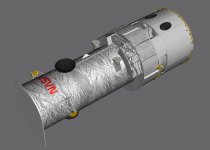
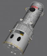
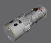
Three preview screenshots of the new HST, in the original launch configuration. Not yet done however, still have add the Magnetic Torque Bars, the EVA handrails, the FWD and aft Low Gain Antennas and the Aperture Door hinges, the third port side trunnion pin and need to close-out work areas on the Aft Shroud.
Attachments
- Joined
- Feb 4, 2008
- Messages
- 9,753
- Reaction score
- 1,024
- Points
- 203
That's the plan. I plan to borrow Donamy's WFC3 and use it as WF/PC-1 with the appropriate modifications.Do you want the HST vessel to have the sensor modules as attachments so they can be replaced during EVA?
Also have to check to whom I sent my SA3 and NCS meshes to.
- Joined
- Feb 4, 2008
- Messages
- 9,753
- Reaction score
- 1,024
- Points
- 203
How's work coming on making the mission files the only source for the ascent AP parameters?
Also, Ku band antenna deploy/stow speed should be changed. Although documentation states that the nominal deploy/stow time of the antenna is approx. 23 seconds, based on timings made of actual deploy/stow time I have made on videos that show the Ku antenna being stowed consistently shows the real timing to be approx. 18 seconds.
Also, Ku band antenna deploy/stow speed should be changed. Although documentation states that the nominal deploy/stow time of the antenna is approx. 23 seconds, based on timings made of actual deploy/stow time I have made on videos that show the Ku antenna being stowed consistently shows the real timing to be approx. 18 seconds.
- Joined
- Feb 4, 2008
- Messages
- 9,753
- Reaction score
- 1,024
- Points
- 203
For the next official public release I think it should be aimed to be more supportive of a complete mission, IE it should have realistic pre-launch/launch ops, on-orbit ops and be capable of stand-alone entry and landing.
This should allow us to identify and eliminate a ton of bugs that surely resides in the code but just haven't been caught yet due to the vehicle not being mission ready.
The initial batch of missions could include the maiden flights of each vehicle(STS-1 for Columbia, STS-6 for Challenger, STS-41D for Discovery, STS-51J for Atlantis and STS-49 for Endeavour).
So we need the DFI pallet and IUS+ASE at least as active vessels.
Once we have this, I think we're ready for another release.
- Joined
- Feb 6, 2008
- Messages
- 38,965
- Reaction score
- 3,937
- Points
- 203
- Location
- Wolfsburg
- Preferred Pronouns
- Sire
I think we should still have a decent release done for Orbiter 2010, and that ASAP.
You are right, a full mission should be the goal, but we are pretty far away still from it. Not alone because of the bugs, that are still not identified, but also by a huge number of missing features. The sensors for the reentry/Landing phase could be done rather quickly, but the whole mess of GPC software around it will not be easy. And if we use a rapid prototyping approach there, we will have to rewrite the GPC software with every new software added. Not really optimal.
You are right, a full mission should be the goal, but we are pretty far away still from it. Not alone because of the bugs, that are still not identified, but also by a huge number of missing features. The sensors for the reentry/Landing phase could be done rather quickly, but the whole mess of GPC software around it will not be easy. And if we use a rapid prototyping approach there, we will have to rewrite the GPC software with every new software added. Not really optimal.
Similar threads
- Replies
- 143
- Views
- 34K
- Replies
- 21
- Views
- 18K
- Replies
- 7
- Views
- 4K