- Joined
- Feb 4, 2008
- Messages
- 9,753
- Reaction score
- 1,024
- Points
- 203
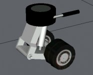
Got it. The hydraulic cylinder shown there, is there another one on the inboard side as well?
Got it. The hydraulic cylinder shown there, is there another one on the inboard side as well?
Got it. The hydraulic cylinder shown there, is there another one on the inboard side as well?
Do you a photo of this arm? I just made it like your modification to the screenshot. I have very little reference images of the wheelsets. They were based off some photos from the Ares 1X stacking last year when the segments were transported from the Surges to the VAB.No, actually the actuator should attach to a small arm, there is not much travel range.
Do you a photo of this arm? I just made it like your modification to the screenshot. I have very little reference images of the wheelsets. They were based off some photos from the Ares 1X stacking last year when the segments were transported from the Surges to the VAB.
Can't make out any details in those photos. Are they really that important considering you can't actually see them unless you move the camera underground? Remember, KSC is very very flat and even. The hydraulic systems is just used to raise/lower the platform for pallet pick up/drop off. Other than that, it pretty much remains even.here is a better view of a similar vehicle:
The tilting actuator seems to be inside the vehicle or a worm drive.
Can't make out any details in those photos. Are they really that important considering you can't actually see them unless you move the camera underground? Remember, KSC is very very flat and even. The hydraulic systems is just used to raise/lower the platform for pallet pick up/drop off. Other than that, it pretty much remains even.
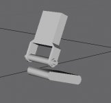
Like this:The actuator does not need to be visible, but I need something to animate properly. Looks like the top part of the bogey is directly attached to the Y-rotation axis, so no additional part is needed, but the bogey needs to be split into an upper and an lower part.
Like this:
New transporter mesh have been checked in. Hopefully this will work.
Checked in a version with the hydraulic actuator removed.Yes, that is useful, but you could have left the hydraulic actuator for rotating the wheel set away, it is not visible in any picture I can find and likely not existing, but instead they used a worm gear. Also the disk above the bogey is pretty flat as far as I can tell.
Could get "sporty" for that. Any special features needed? For this release we're aiming for mission completion, IE that you can fly a mission from pre-launch to wheelstop on the runway.Does anyone think we could have a release, for Orbiter 2010 in time for STS-133 ? I'd like to get the payload working for that mission.
So for that we need at least a working GLS and a working comm system. I believe we were thinking about prototyping the comm system in the C/T before putting in the shuttle.
Just wanted to check on this. How is the fix coming along? I think some of the VC positions in the orbiter needs the same treatment as well.Currently we have a problem with camera direction when switching cab views. Seems like we have to add some additional code per Martin here: http://orbiter-forum.com/project.php?issueid=544#note3477
Works perfectly now, thanks! BTW, could you add a function that logs G's over time during launch? I have found a generic SSME throttle curve diagram that could help us nail down why we are MECO'ing some 45 seconds early compared to the real shuttle.Just checked in a fix (for the shuttle and Crawler).
Works perfectly now, thanks! BTW, could you add a function that logs G's over time during launch? I have found a generic SSME throttle curve diagram that could help us nail down why we are MECO'ing some 45 seconds early compared to the real shuttle.
I think we're running too hot somewhere and this diagram could help us nail down if we're hitting milestones too early during ascent. If it helps, the sample time is every 5 second starting at T0 with G's being every 0.25 G.