- Joined
- Feb 4, 2008
- Messages
- 9,753
- Reaction score
- 1,024
- Points
- 203
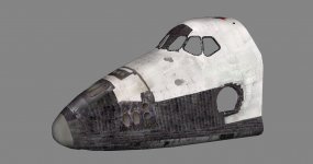
What kind of seams are we talking about here? Could you send me an uncut version of the fwd fuselage minus the FRCS? I want to try cutting it in GMAX to see if it handles it better.No, things can always be remapped. The distortion is cused by vertices that get moved around during the mesh cutting. It can cause unsightly seams to appear on the model.