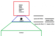
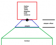
First time commenting, so I kinda feel I'm butting in, but I think the spacecraft deserves it's own offset, without any odd ties to the adapter. I don't have a suggestion in mind, but what I worry about is having a clunky system that works well on the developer side but falls short on user friendliness. If the payload is too long or too short to fit in adaptor*2, or if moving the attachment also moves the adapter around, one thing I see happening is having to open up the payload's .cfg and edit it's attachment point around so it fits SSU- meaning I'll having to edit two files to add a payload to Centaur, rather than fiddle with only one.