Centaur G/G Prime High Energy Upper Stage


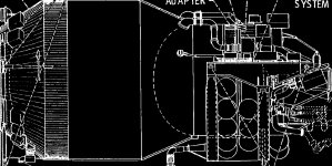
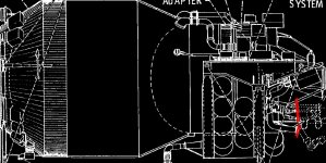
Just completed modeling to point complete enough that would allow me to test the telescoping pipe idea and it works. We're going to need a scaling animation along with the main Deployment Adapter rotation animation though for the telescoping part.

Why scaling? Shouldn't it already work by just a rotation alone?

I can't volunteer for coding, though I would like to. I currently work on moving the AP-101S stuff into a separate project and separate DLL, so I don't disturb the main SSU development for such a complex project. If the AP-101S emulation works there and is tested well, we can still include it as option or primary method.
 
Bad news again: I thought I had it but failure once again. I don't know what to do now.

---------- Post added 02-27-11 at 03:32 PM ---------- Previous post was 02-26-11 at 11:44 PM ----------

Here's a animation video of the CISS LH2 fill/drain plumbing rotation in GMAX. It shows the problem quite clearly. The reference image in the background is from a documented dated April 1987, so it is of the final Centaur/CISS designs. Any ideas for improving the look?

 
make the hose all one piece, and place the rotation point slightly to the left.
 
make the hose all one piece, and place the rotation point slightly to the left.
You mean slightly to the left of its current pivot point? Currently the pivot point for lines is at the Deployment Adapter pivot point.

Also, by "the hoses all one piece" do you mean the ones rotated in the video?
 
From what I thinmk I'm seeing, you have the yellow tube in two pieces. If you join them and move the rotation point to the left it will cause the lower part to go into the box, but the upper part won't look like it's breaking. If that's clear?
 
From what I thinmk I'm seeing, you have the yellow tube in two pieces. If you join them and move the rotation point to the left it will cause the lower part to go into the box, but the upper part won't look like it's breaking. If that's clear?
Yes, that's clear. Actually it is four cylinders, the upper horizontal cylinder and its bellow, then the 90 degree bend and then a straight vertical cylinder that connects the other three with the lower bend. According to my analysis the lower bend does not move.
 
That maybe so, but very difficult to animate.
It has to remain stationary or it will impact the aft center U structure.
 
Why don't you put the break into the lower bend (as seen from the side)?
 

Attachments

  • CISS schematic 2.jpg
    CISS schematic 2.jpg
    304.9 KB · Views: 687
Why don't you put the break into the lower bend (as seen from the side)?
As I wrote: That bend doesn't move at all. Could you once again indicate where you would want the break?
 
Well, looking at the differences in stroke, lets put disconnects at these points.

I doubt that the Shuttle has to be able to dump the stage fuel tanks while in orbit and with the stage deployed (because there is a much simpler thing available: jettison the stage)
 

Attachments

  • CISS schematic 2 (cut).JPG
    CISS schematic 2 (cut).JPG
    171.1 KB · Views: 685
Oh, I see better now. How about rounded at the bottom end and pivot it there ?
 
Well, looking at the differences in stroke, lets put disconnects at these points.

I doubt that the Shuttle has to be able to dump the stage fuel tanks while in orbit and with the stage deployed (because there is a much simpler thing available: jettison the stage)
Actually, propellant dumping would be done in case if a No Deploy scenario in the event of a SuperZip failure or other anomaly. Except for the Centaur forward trunnion pins, the CISS trunnions pins were secured to the orbiter by standard orbiter inactive payload latches.

So getting rid of the CISS/Centaur would have involved alot of complex EVA activity which I don't think any of the STS-61F or SS-61G crew members received.

---------- Post added at 06:21 PM ---------- Previous post was at 06:06 PM ----------

Oh, I see better now. How about rounded at the bottom end and pivot it there ?
:hmm: I think you're on to something here! I just can't understand the clean room photo. It just doesn't show any hemispheres.
 
Actually, propellant dumping would be done in case if a No Deploy scenario in the event of a SuperZip failure or other anomaly. Except for the Centaur forward trunnion pins, the CISS trunnions pins were secured to the orbiter by standard orbiter inactive payload latches.

Yes, but I don't yet understand what the problem with this is. The disconnects would remain connected (maybe already closed, maybe not) until the active latches are signaling open. Then you move to deploy the Centaur into separation attitude, disconnecting the disconnects along the way.

So getting rid of the CISS/Centaur would have involved alot of complex EVA activity which I don't think any of the STS-61F or SS-61G crew members received.

Not really that complex. The only problem you would need an EVA for, is if the deployment stops halfway along the way or the stage does not separate. Until the disconnects moved far enough away, they would remain properly connectable, Also there is still a 99% chance that a disconnect could reconnect if you retract the CISS.
 
Just did some experimentation and it seems like if I make the upper pipes the same diameter I can get the upper pipes to hide the hemisphere when in the lowered position. Now it is just to find the diameter value that agrees the most with the photos.
 
Yes, but I don't yet understand what the problem with this is. The disconnects would remain connected (maybe already closed, maybe not) until the active latches are signaling open. Then you move to deploy the Centaur into separation attitude, disconnecting the disconnects along the way.


Not really that complex. The only problem you would need an EVA for, is if the deployment stops halfway along the way or the stage does not separate. Until the disconnects moved far enough away, they would remain properly connectable, Also there is still a 99% chance that a disconnect could reconnect if you retract the CISS.
I have attached the Centaur launch sequence as illustrated in Jenkin's Space Shuttle book, 3rd edition, p. 245.
 

Attachments

  • Centaur_Launch-Sequence.jpg
    Centaur_Launch-Sequence.jpg
    258.9 KB · Views: 863
So it uses this for fluid transfer:

[ame="http://en.wikipedia.org/wiki/Collet"]Collet - Wikipedia, the free encyclopedia[/ame]

The question is just, where.
 
Back
Top