Space Shuttle Ultra 1.25 Revision B development

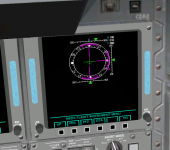
jevans: Did you already see the MDU soft button menu structure(page 6-3)? The PFD display modes are easily explained by this structure, if you look at your cockpit photograph, you can see that the two PFD modes are having different selections in the menu... and are obsolete.

One should be A/E PFD, the other Orbit PFD. These displays in the photograph are already the old never flown version.
 
Oh, I see what you mean. I couldn't make sense of that table compared to most of the pictures. I suppose they decided to combine the displays after all the publicity shots went out...

There are two other simulator projects that I know of that simulate MEDS( one for orbiter, one standalone) and both do it the 'wrong' way.

If the split displays never flew, then obviously the simpler single display is the way to go, as detailed in the SCOM. Now all I have to do is code it!:thumbup:
 
Just for reference from the ascent checklist, today the displays are configured as such during ingress:

MDU|View Angle|Port Config|Selected Port|Flight Critical Bus|Display|Edgekey Menu
CRT1|positive|auto|primary|3|DPS|DPS
CRT2|positive|auto|primary|4|DPS|DPS
CRT3|positive|auto|primary|4|DPS|DPS
CRT4|negative|auto|primary|1|DPS|DPS
CDR1|positive|auto|primary|3|OMS/MPS|FLT INST
CDR2|positive|auto|primary|3|A/E PFD|DATA BUS
MFD1|positive|auto|primary|3|HYD/APU|SUBSYS STATUS
MFD2|positive|auto|primary|4|OMS/MPS|SUBSYS STATUS
PLT1|positive|auto|primary|4|A/E PFD|DATA BUS
PLT2|positive|auto|primary|4|HYD/APU|SUBSYS
AFD1|negative|auto|n/a|n/a|n/a|n/a
 
So, here's a first shot of the On-Orbit ADI ball screen.

Obviously, the one thing that's missing here is the actually ADI ball itself! I'm a bit stumped as to how to actually render that in GDI - any ideas?
 

Attachments

  • previewmeds1.PNG
    previewmeds1.PNG
    284.6 KB · Views: 520
Obviously, the one thing that's missing here is the actually ADI ball itself! I'm a bit stumped as to how to actually render that in GDI - any ideas?

Option 1: Use Direct3D for painting the ADI ball, but this would mean for compiling the SSU sources, we would need the DirectX SDK...which is pretty immense. Alternatively, you can use OpenGL, which needs less prerequisites for compiling, but might be a tiny bit slower.

Option 2: Do a software implementation of flat hidden face removal, painting on a memory bitmap... it requires a bit more of thinking, but could be as fast as the Direct3D approach.

I know that I would prefer Option 2, but I am deeply afraid of the effort needed to get the rendering right and effective enough, so only those elements are drawn, that are visible.
 
I quickly concluded Direct3D would be a bad idea, although easier from a rendering point of view.

The annoying thing is that I think this can be done easily with the new 2D panel orbiter API - I think Martin has done something similar for the new Shuttle A panel - http://www.orbiter-forum.com/showthread.php?t=18223&highlight=shuttle+adi

I wonder if we could do something similar?

I'm thinking about some sort of polar coord mapping on a bitmap image might work? I'll go and revise my vector maths...
 
I quickly concluded Direct3D would be a bad idea, although easier from a rendering point of view.

The annoying thing is that I think this can be done easily with the new 2D panel orbiter API - I think Martin has done something similar for the new Shuttle A panel - http://www.orbiter-forum.com/showthread.php?t=18223&highlight=shuttle+adi

I wonder if we could do something similar?

Doesn't work for MFDs, only for Panel2D elements, which are essentially flat billboard meshes.

You won't need polar coordinates in the code, if you use an array of VECTOR3 vertices that you transform by a rotation matrix. After the rotation, you ignore all negative(or positive) Z coordinates, could select X/Y coordinates and check X*X + Y*Y < R² for clipping...clipping will be very likely the toughest part.

Since processing an array of 1000+ points would be pretty much useless effort, I would optimize then selecting a smaller set of vertices from the full set first, and calculating the full set only for those regions of the ADI sphere, that are actually needed. Essentially, you divide the sphere into triangle (poles) and quad patches, and check only the corner points of these patches, if they are really visible, if one edge is visible, you process and draw the full set in this patch...etc.
 
Last edited:
I suspect the easiest thing might be just to use basic drawing operations - it should be easy enough to get all the lines/shading correct, and we can either have the text vertical or use a rotated font.

---------- Post added at 09:18 PM ---------- Previous post was at 09:09 PM ----------

Take a look at the Draw functions in the graphics class. This should be enough for the ADI ball, and I don't think the text will be a problem.
http://msdn.microsoft.com/en-us/library/ms534453.aspx
 
Urwumpe: Just a heads-up, I think you forgot to check in the complete sources for the VAB. Right now only the project file is checked in. Pay this no mind if this is what you intended.
 
I thought we were only using GDI, not GDI+? Are we allowed to use it?

I've got an idea for how it could be done - I'll try it tonight.

---------- Post added at 07:04 AM ---------- Previous post was at 06:55 AM ----------

Also, should I get the actual values for the ADI from Orbiter directly, or should I get them from the DAP?
 
Urwumpe: Just a heads-up, I think you forgot to check in the complete sources for the VAB. Right now only the project file is checked in. Pay this no mind if this is what you intended.

Was intentional, I am currently working at a Lua interface for handling the VAB animations. I decided that using scripts or the Lua console is better for the beginning, since we could then use the Lua interface for handling assembly operations.

Didn't want to commit something half finished there, but for adding the second wave of VAB files to the local copy, so I don't forget a file again, I had to commit the folder first.

---------- Post added at 09:28 AM ---------- Previous post was at 09:23 AM ----------


Also, should I get the actual values for the ADI from Orbiter directly, or should I get them from the DAP?

You would get them from the IDP. I have read somewhere a definition, which words are send over a FC bus to the IDP, just like they had been send to the old analog cockpit indicators of the dedicated display system.
 
Last edited:
Ok, I can't get blitting of bitmaps to work:
Code:
int Save=SaveDC(hDC);
        HDC CompatibleDC=CreateCompatibleDC(hDC);
        HDC BitmapDC=CreateCompatibleDC(hDC);
        SelectObject(BitmapDC, adibit);
        HBITMAP BMP=CreateCompatibleBitmap(hDC, 256, 256);
        SelectObject(CompatibleDC, BMP);

        BitBlt(CompatibleDC, 0,0, 256, 256, BitmapDC, 0, 0, SRCCOPY);

        BitBlt(hDC, 0, 0, 256, 256, CompatibleDC, 0, 0, SRCCOPY);

        RestoreDC(hDC, Save);
        DeleteDC(CompatibleDC);
        DeleteDC(BitmapDC);
        DeleteObject(BMP);

'adibit' is defined as the bitmap, loaded from resources. This code just seems to blit black all the time. Any ideas?
 
The SelectObject for the bitmap feels wrong, isn't this done for selecting pattern brushes?

You should create the bitmap by loading it.
 
The SelectObject is used for selecting brushes, but it also seems to be used here, too.

The image is being loaded earlier on in the code - I've tried to convert this code from the code used to blit the DPS displays to the screen, as they use a bitmap font blitted to the screen. I can't get it to work here, though. What I'm trying to do is just get it to blit a bitmap to test it first, and then I'll replace the blit by a pixel-by-pixel blit mapping function that I've worked out for the ADI ball. I think it will create the desired effect of the curved ball in 2D, but I can't do it with no bitmap.:facepalm:

What I can't work out is why there's no command to just draw a bitmap into an hDC - you can only blit from one buffer to another, it's getting the bitmap into the buffer that seems to be the problem.
 
I thought we were only using GDI, not GDI+? Are we allowed to use it?

I've got an idea for how it could be done - I'll try it tonight.

---------- Post added at 07:04 AM ---------- Previous post was at 06:55 AM ----------

Also, should I get the actual values for the ADI from Orbiter directly, or should I get them from the DAP?
You might have to add a few headers, but I don't see any reason not to use GDI+.
 
Thank you. Now the only thing missing is the pad hiss noise! Then I think we can call the pad done for now and can move on to other things. Oh and more control over the various swing arms in the pad control dialog window. Like the GVA, OAA and the GH2 vent line.
Just thought I would give this a bump, now that rollout operations have been implemented.
The controls for the actual GOX Vent Arm and Vent Hood should be separate as they're mechanically independent from each other.

---------- Post added 12-08-10 at 06:02 AM ---------- Previous post was 12-07-10 at 06:39 AM ----------

Did another entry, which was just another failure. This time it was around Mach 2.3. I don't know about any of you but I'm getting pretty tired of these constant aerodynamic problems. Noticed something though, it switched over to CSS just as the elevons got saturated.
 
It switches to CSS at Mach 2.5. If you just let the vessel fly by itself at that point, it'll try to hold the same pitch, which it might not be able to do.
 
It switches to CSS at Mach 2.5. If you just let the vessel fly by itself at that point, it'll try to hold the same pitch, which it might not be able to do.
OK. Couldn't it be changed to maintain a zero degree elevon angle instead of totally freaking out and saturating the elevons?

I guess the same question applies for early entry with roll rate, the AoA AP maintaining a zero deg/s roll rate and instead of reacting immediately it responds to a commanded roll angle.
The pitch needs to be controlled somehow - maintaining a zero degree elevon angle would cause the shuttle to either pitch up (and stall) or dive towards the ground. IMHO, once the autopilot ends at M2.5, the best thing is to downmode to CSS and have the user take control.

With roll, the problem is that there's no good way to set the aileron position (because we're still using CreateControlSurface for the ailerons). I'm in the process of creating a csv data file for the ailerons.
 
Back
Top