The Universal Flight Simulator

Hey guys,
Progress report 2024-W38:
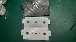
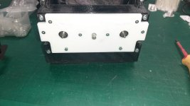
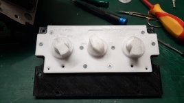
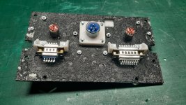
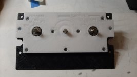
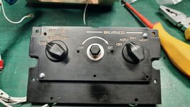
  1. Developing and prototyping of HUD control panel is still on going. Results are satisfactory. Minor design modifications required.
  2. Selected rotary switches have not sufficient rotational torque in conjunction with d30mm knob. The article to be replaced with a switch with higher rotational torque. A possible replacement found and ordered.
 

Attachments

  • Front panel 3d printed prototype 01.jpg
    Front panel 3d printed prototype 01.jpg
    120.9 KB · Views: 5
  • Front panel 3d printed prototype 02.jpg
    Front panel 3d printed prototype 02.jpg
    93.3 KB · Views: 5
  • Front panel 3d printed prototype 03.jpg
    Front panel 3d printed prototype 03.jpg
    84.8 KB · Views: 6
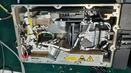
  • Back of the panel.jpg
    Back of the panel.jpg
    176.4 KB · Views: 6
Last edited:
Hey guys,

Progress report 2024-W39:
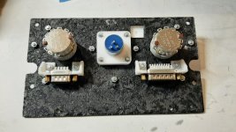
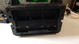
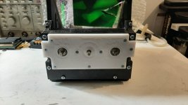
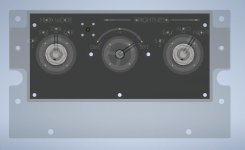
  1. Revised HUD control panel is ready to suit larger rotary switches. Mounting hole patterns were optimized.
These parts are 3d printed for prototyping purposes. The final article will have laser cut/engraved parts made of 3mm thk Perspex with thin (0.8mm thk) PCB sandwiched between them for providing a backlight circuitry.
 

Attachments

  • Updated HUD panel - front.jpg
    Updated HUD panel - front.jpg
    60.5 KB · Views: 6
  • Updated HUD panel - back.jpg
    Updated HUD panel - back.jpg
    139.9 KB · Views: 6
  • Updated HUD panel - main enclosure.jpg
    Updated HUD panel - main enclosure.jpg
    87.5 KB · Views: 6
  • Updated HUD panel - installed without knobs fitted.jpg
    Updated HUD panel - installed without knobs fitted.jpg
    87.5 KB · Views: 7
Last edited:
Hey guys,

Progress report 2024-W40:
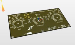
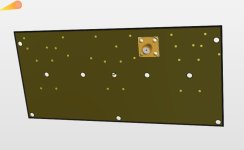
  1. Backlight PCB for HUD control panel is finished. Ready to be ordered.
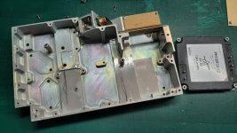
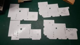
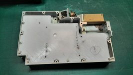
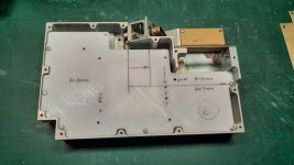
  2. I have started to fit my custom PCB in existing Power supply enclosure for the HUD. It took me 6x tries until it fit perfectly, and all mounting holes are aligned. The main issue was that the enclosure itself has very uniform shapes and cannot be measure reliably by hand to create an accurate 3d model.
 

Attachments

  • Power supply enclosure and new DC-DC module to fit.jpg
    Power supply enclosure and new DC-DC module to fit.jpg
    117.1 KB · Views: 7
  • PCB shape adjustment attempt 1 thru 4.jpg
    PCB shape adjustment attempt 1 thru 4.jpg
    63.7 KB · Views: 7
  • PCB shape adjustment attempt 5 - getting there.jpg
    PCB shape adjustment attempt 5 - getting there.jpg
    96.3 KB · Views: 7
  • PCB attempt 6 - finally, height clearances indicated.jpg
    PCB attempt 6 - finally, height clearances indicated.jpg
    117.7 KB · Views: 9
  • Hud control panel PCB (see thru).jpg
    Hud control panel PCB (see thru).jpg
    42.6 KB · Views: 9
  • Hud control panel PCB - top layer.jpg
    Hud control panel PCB - top layer.jpg
    49.2 KB · Views: 9
  • Hud control panel PCB bottom layer.jpg
    Hud control panel PCB bottom layer.jpg
    17.7 KB · Views: 9
Last edited:
Hello everyone,

Progress report 2024-W41:

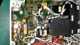
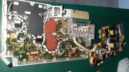
1. I've decided to use as many electronic components from original HUD electronics as possible. There are a lot of top notch capacitors, op-amps, transistors, etc. which can be easy implemented in my circuit design plus it will cut an overall BOM cost down as I have paid for that HUD unit already anyway. So basically I've spent all last weekend de-soldering parts and adding them to my pcb libraries for future use.

I've attached original SMPS board photos for reference.
 

Attachments

  • Original power supply pcbs 01.jpg
    Original power supply pcbs 01.jpg
    180.1 KB · Views: 10
  • Original power supply pcbs 02.jpg
    Original power supply pcbs 02.jpg
    156.7 KB · Views: 12
Last edited:
Hi guys,

No major progress was made during 42nd week :) I've got my wife's Birthday on Friday and Dream Theater's show on Sunday haha \m/
 
Hi guys,
Progress report 2024-W42-48:
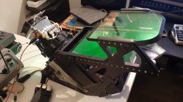
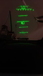
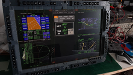
Slowly getting HUD ready got the pit. Last weekend got a successful test of LCD+backlight+optics+combine for the fist time.
Very nice visibility of the projected symbology even in direct sunlight.
Still working on pcb's for the unit.

PS. Sorry for blurry photos, my phone refused to capture it clearly...
 

Attachments

  • Over view of the test article.jpg
    Over view of the test article.jpg
    101.8 KB · Views: 26
  • Night setting.jpg
    Night setting.jpg
    14.6 KB · Views: 25
Last edited:
Hey guys! Long time no see haha
Finally real progress has been made building the HUD. Both hardware and software-wise. For later I cant thank @JDat enough for his valiant effort for creating an external HUD script to run it on raspberry pi. It's not just a copy of the Orbiter generated HUD on an external screen. Our plan is to feed the data from Orbiter via Orb:Connect over the ethernet and draw all symbiology from the scratch on the Pi directly, reducing the lag and increasing the frame rate considerably.. I let him to explain all details :)
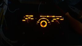
From my side, I've finished all internal wiring and it's all ready to go. What's left are couple side covers, changing cracked and chipped main combiner glass and re-do front control panel - first iteration is fine, but no cigar - lettering is too deep and not that crisp + hot spots from individual leds are visible ,but it gets the job done for a time being.
Some pics are attached.
A short video of yesterday's test is below:
PS. the mid brightness knob on the front panel shown of the photos is fitted temporary and already replaced with proper sized one.
 

Attachments

  • Front panel test article 02.jpeg
    Front panel test article 02.jpeg
    30.9 KB · Views: 13
  • Front panel test article 01.jpg
    Front panel test article 01.jpg
    101.2 KB · Views: 12
  • Main harness.jpg
    Main harness.jpg
    119 KB · Views: 12
  • Top view.jpeg
    Top view.jpeg
    145.9 KB · Views: 10
Hi guys!
Fresh quick updated straight from the JDAT's lab, looks like data connection between Orbiter and the external "symbol generator" is working! All data transfered over ethernet using Orb:Connect.
Not all functions are implemented yet of course, but it is a huge milestone:


Again, massive thanks to @JDat !!
:hailprobe:
 
Little update on the external HUD:
@JDat and I (mostly @JDat!) keep polishing the surface HUD.
Some symbols added (velocity, vertical velocity, altitude, AoA, G-force, Mach number, gear down indicator), but they are static (hardcoded) for now.
Pitch, bank and azimuth angles are working now, getting live data from the Orbiter.
Velocity vector is a stubborn one! Still doesn't work as intended.. Its scale is off big time comparing to Orbiter's on screen HUD.

A short video clip of the HUD in action:
 
Last edited:
Sharing some backstage footage without @Phil Smith permission. 🤫 Who said that VNCMFD addon is useless? Button cougar software and remote multiMFD in development...

View attachment 45379
Cool! Is that two Cougar MFDs sliced and diced? I'm wondering how you rearranged the buttons to display on the perimeter in each MFD.
 
It's little different... Designed by @Phil Smith . I only throw basic idea and made some software experiments. That 4xMFD actually is Raspberry Pi. Buttons are connected directly to Raspberry Pi GPIO. Then there are 5 windows opened. In center it is web browser window. Web browser interact with Oriber addon (don't remeber name, made by kamaz related web) 4x small VNC clients. You know that remote desktop stuff and similar modern technologies. So, 4 little customized VNC clients, that read GPIO buttins and translate them into virtual mouse click. That's how VNC internals working. Next: there Orbiter addon named VNCMFD (or similar). You can configure button layot for VNCMFD addon in a way you need. So VNCMFD have 4 congurations, each own button layout. As result your Raspberry Pi run 4 VNC clients and connect to Orbiter. Then Get correct image in realtime from Orbiter. Also sent virtual mouce click every time you press button. Don't worrky about dodgy mouse mentions here. You normally don't need real mouse here for Raspberry Pi. No accidental mouse clicks. Or... If you want, you can use mouse. For example when startin Raspberry and need to pistion windows in correct locations. Also if you want (and don't have real GPIO buttons), you can use mouse on Raspberry Pi to click on MFDs.

I really like this technology, because it's not depend on USB and old hardware. You can build everything yourself. And, most interesting, and important, it all happening over Ethernet (LAN), no dirty hacks. Solid and clean connetion between Orbiter PC and Raspberry Pi.

Kinda like this...

In future tere was plans to redesign VNC viewer client, but no tme and no mitivation for now.

There are also unfinished software for external HUD project. You can get HUD image on external display. Remaining is mechanics, but as result you can make almost real semitransparent HUD like in real shapce shuttle or aircraft.

 
Back
Top