SSU Development thread (4.0 to 5.0) [DEVELOPMENT HALTED DUE TIME REQUIREMENTS!]

Status
Not open for further replies.
Which axis should the belly band of the texture wrap around? I need something identifiable to be align the texture properly.
The vertical triple line in the texture should be in the y = 0 plane, and should go all the way around. The top and bottom of the texture should meet.

---------- Post added at 11:23 PM ---------- Previous post was at 11:22 PM ----------

I did this years ago for the Gemini, but it never got used.

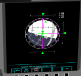
Hopefully we'll need something like that for the MCDS cockpit sometime in the next decade.
 
It's not wrapped the right way... the poles of the ball should be the (0, 256) for the -x axis, and (256, 256) for the +x axis.
On the positive side, the point (128, 256) is in the correct place in the -z axis.
Try it now. I think I have it the correct way now.
 
Try it now. I think I have it the correct way now.

Ok, now it's wrapped correctly! The axis were not right so I had to use Shipedit to rotate +90º on the z axis, and there are some small issues with the wrapping that don't really matter for now.
Thanks! :cheers:
 
This is whats inside the Gem ADI.
 

Attachments

  • ADI.jpg
    ADI.jpg
    31.6 KB · Views: 468
This is whats inside the Gem ADI.

It might not have looked like that. On Apollo and the Shuttle, the "poles" of the ball were on the sides (+/-90º yaw) and not on the top and bottom (+/-90º pitch). The vertical band (in relation to the horizon) was actually a slot from where the ball was held and rotated. I really don't know how it was on Gemini... it had a different contractor, so it could have been different.
 
This would indicate you are correct.
 

Attachments

  • 25-hi.jpg
    25-hi.jpg
    328 KB · Views: 561
This would indicate you are correct.

No, actually your model is correct and it really was different from what came after. This one has the poles on the top and bottom, so pitch +90º would show one of the poles right in the center. If you look up one from Apollo (and they were later reused on the Shuttle) you'll see that they are different, the poles will be on the border between the white and black areas, as opposed to this Gemini ball where the poles are in the middle of the white and black areas.
 
Gemini had a four axis IMU, which made it immune to gimbal lock, on Apollo, the gimbal lock regions had been especially pronounced on the ADI.
 
Last edited:
So, here's the initial result.
I think the mesh will have to be made smoother, and the texture near the poles will have to be distorted somehow so that when rendered the numbers won't look squeezed like they do.
I'll increase the texture size from 512 to 1024 or 2048 to get it to look sharper. Performance question: is there any gain breaking the texture into 2 parts? Each part would use up most of the texture area, instead of having 50% of the texture being unused. Basically, are 2 squares better than 1 rectangle?
 

Attachments

  • meshADI.PNG
    meshADI.PNG
    107.4 KB · Views: 562
So, here's the initial result.
I think the mesh will have to be made smoother, and the texture near the poles will have to be distorted somehow so that when rendered the numbers won't look squeezed like they do.
I'll increase the texture size from 512 to 1024 or 2048 to get it to look sharper. Performance question: is there any gain breaking the texture into 2 parts? Each part would use up most of the texture area, instead of having 50% of the texture being unused. Basically, are 2 squares better than 1 rectangle?

Absolutely yes. It makes no sense to force a single rectangular texture on it. For much better readability of the letters and numbers, it would also make sense to make them use their own texture and render them as separate quads on the globe.
 
New ADI committed!
I tested having all 11 MDUs showing that and still got over 60 fps, so it seems to be really cheap! :thumbup:
 
New ADI committed!
I tested having all 11 MDUs showing that and still got over 60 fps, so it seems to be really cheap! :thumbup:

Lets see if we can also so that with the DPS screens. :thumbup:
 
I'm getting this error message when I try to compile the latest SSU beta sources:

Code:
vc\MDU_OrbitPFD_Display.cpp(806): error C2039: 'DrawSketchMesh' : is not a member of 'oapi::Sketchpad2'
1>          E:\SSU_beta\Orbitersdk\include\Sketchpad2.h(28) : see declaration of 'oapi::Sketchpad2'

I'm using the SDK files from this post: http://www.orbiter-forum.com/showthread.php?p=535151&postcount=3875

---------- Post added at 02:57 PM ---------- Previous post was at 02:56 PM ----------

Lets see if we can also so that with the DPS screens. :thumbup:
Even before the DPS screens were no issue. It was the MEDS displays that were hogging all the FPS.
 
Even before the DPS screens were no issue. It was the MEDS displays that were hogging all the FPS.

I know, but it was a fight to get it that far, I remember the DPS screens consuming quite a lot of FPS before optimizations. Also I remember reading about poor rendering quality now in the DPS screens, so we have to improve it anyway.

It just makes sense to also move the DPS screens on the same base now and see if we gain some more FPS that way as well. The less we need for rendering the screens, the more CPU time we can invest into subsystems and support systems.
 
I'm getting this error message when I try to compile the latest SSU beta sources:

Code:
vc\MDU_OrbitPFD_Display.cpp(806): error C2039: 'DrawSketchMesh' : is not a member of 'oapi::Sketchpad2'
1>          E:\SSU_beta\Orbitersdk\include\Sketchpad2.h(28) : see declaration of 'oapi::Sketchpad2'

I'm using the SDK files from this post: http://www.orbiter-forum.com/showthread.php?p=535151&postcount=3875

Use this one instead http://www.orbiter-forum.com/showthread.php?p=535595&postcount=3892
 
Thanks, I deleted the gcAPI_dbg.lib and it compiled fine. Although now I get a CTD when trying to use the Orbit PFD. The moment I click on the edge button for the Orbit PFD, it's an instant CTD.

I just compilled the Release config and the Orbit PFD worked on all 11 MDUs... could you try the debug and attach to the process to see where it CTDs?
 
I just compilled the Release config and the Orbit PFD worked on all 11 MDUs... could you try the debug and attach to the process to see where it CTDs?
Debug breaks at line 807 in MDU_OrbitPFD_Display.cpp.
 
Status
Not open for further replies.
Back
Top