whitewatcher
New member
- Joined
- Jun 2, 2008
- Messages
- 23
- Reaction score
- 0
- Points
- 0
Hello together,
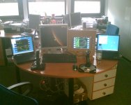
just yesterday I have finished a Client-Server-MFD system. How it works:
1.) You compile my "NetMFD.cpp" into your spacecraft-dll.
2.) You give your spacecraft-dll a list of IP-adresses (one for each MFD)
3.) You install the MFD-Server on each of your laptops. I'm using some 400Mhz laptops with WinXP and it works just fine. I even have an USB-IO/Flatpanel interface built in my Server.
4.) You start Orbiter and press F8. The panel initialization routine of your S/C will register the MFDs to Orbiter and stablish a network link to your laptops.
The protocol is TCP based and very simple. I believe implementing a Linux Server would be very easy.
H/W-List for a complete MFD:
- Laptop
- Flatpanel
- USB I/O-Card (Quancom USBTTL24)
- 15 pushbuttons
- panel plate with cutouts
- some 1k-Resistors, cables, .....
If you are interested, I can give you some photos and additional information (drawings, documentation, ...). Contact me under [email protected].
Attachments
Last edited:
")
")