Project H-10-K Enterprises Gateway Station

^Continued

GNC(started with this and then lengthened, and replicated griebles for the other modules)
Power module(55 ft long, is the largest pressurized module on station)
Elbow for Hab(the module is 9ft diameter, and with the 22.5 degree joints, it makes for a very tough module to model.)
 

Attachments

  • GNC.jpg
    GNC.jpg
    98.1 KB · Views: 43
  • Power Module.jpg
    Power Module.jpg
    118.4 KB · Views: 43
  • Elbow.jpg
    Elbow.jpg
    98.3 KB · Views: 51
Coming together nicely, I'd say!

Those beautiful handrails...are they attached before or after the module's in orbit?
 
Awesome meshes! Great, Quality work as always.
 
Coming together nicely, I'd say!

Those beautiful handrails...are they attached before or after the module's in orbit?

Before, Attaching so many hand rails after launch would create an inordinate quantity of EVAs. Each module will fly inside a fairing, mounted atop the proper sized booster. In the case of the X module, one of the heaviest @ 42,500 lbs or 21.5 Tons, A Delta IV Heavy, 5m booster will only take 28,620 lbs, So I'm still looking for a booster that can handel the weight.

On a side note, I also need a booster that can handel the 60ft length of the Battery Rack Module.

Finding boosters, is not easy since Constellation was scrapped, and the SLS is on the drawing board. I was hopeing a nice Falcon X Heavy with 248,019 lbs capacity would solve my heay lift problems. But it's still a ways off, as it too is on the drawing board.
 
I am a little late to this party but this is an impressive project, and its seems to be coming along nicely. Excellent work Capt hensley.
 
It's just meshes so far, but thanks, the real excitement comes when we go to coding these modules up for use. I'll need lots of help.
 
GWS Update, more meshes

I've been sick all weekend, it's a real bad reaction to all the mold from the flooded Missouri river. No worries, I'll pull through.

Gimbal A: contains a TEE module adapter, although it's equipped to be pressurized, the CBM hatches will remain closed, and the module will remain un-pressurized. It's primary function is to provide the interconnect for the solar arrays current. I used the NASA ISS model gimbal A because it's free, and why reinvent the wheel. Inserting the TEE adapter was fun enough as it was. It's secondary purpose is to facilitate the berthing of the GNCs and Prop modules using ACBM's at it's 0 and 180 degree ports. (I've mistakenly used PCBMs here, I was sick so shoot me. It'll be right on the final model)

The Graviton: this module is physicaly split into two sections. It allows and facilitates the rotation of the Hab Wheel. I split this module in 3DS as well so it can be animated in the future. No I still don't really know how to make the rotating umblical connections for Gases, Power, and liquids. But I'm confident an engineer could come up with a viable solution. However the rotation is presented by a gearing and redundant motor system on the interior walls of the module. Most likely it will be simalr to the Gimbals used by the solar arrays.

Ladder modules: the longest of the small diameter modules with atmosphere tanks. They can serve as airlocks if needed. No storage. This is where the gravity of the rotation become evident. The climb up gets easier, while the climb down get harder. The tanks are placed closer to the hub node to keep the weight on the wheel at a minimum.

MPLM: although slightly longer than the ISS MPLM, it serves the same purpose. It's longer to allow it to be permantly installed on Gateway. It is insulated and equipped just like a standard module, however, it is a terminating module, in that it has only one CBM and all umbilicals are terminus adapted.

Short Airlocks(Short Airlock): This is simply a connecting module equipped with PCBMs. It's used at the tank modules, and the docking facility.

The X Module: the other major module making up the back bone of the race track design.

The X Tunnel(Shaft Airlock): it's the same length as an X module. So why not just use a full diameter X module? Well two reasons, 1. my plastic model uses them, 2. I didn't feel that I needed 4 more major modules on the station. But they do allow for the expansion if desired later in the 50 year life of Gateway. The tanks are for atmospheric gasses. These tanks can be flown up to allow for temporary pressurization of the station, until the bulk gasses can be flow by logistics ships at a later time, that will fill the large ET mods.

Enjoy!
 

Attachments

  • Gimbal A.jpg
    Gimbal A.jpg
    137.8 KB · Views: 50
  • Graviton.jpg
    Graviton.jpg
    109.6 KB · Views: 31
  • MPLM.jpg
    MPLM.jpg
    91.4 KB · Views: 22
  • Ladder.jpg
    Ladder.jpg
    102.3 KB · Views: 27
  • Short Airlock.jpg
    Short Airlock.jpg
    100.1 KB · Views: 22
  • X Module.jpg
    X Module.jpg
    101.8 KB · Views: 24
  • X Tunnel.jpg
    X Tunnel.jpg
    124.2 KB · Views: 33
No I still don't really know how to make the rotating umblical connections for Gases, Power, and liquids.

The only ideas I can come up with are either maintenance nightmares, would have too much leakage, or would impact greatly on habitable volume, but that last one is probably the best solution: Run all the cables and pipes through the axis of rotation, i.e: the center of the module. Where the ladder modules attach (presumably in the next module) it should be fairly simple to split the pipes into 4 at a rotating junction.
 
The only ideas I can come up with are either maintenance nightmares, would have too much leakage, or would impact greatly on habitable volume, but that last one is probably the best solution: Run all the cables and pipes through the axis of rotation, i.e: the center of the module. Where the ladder modules attach (presumably in the next module) it should be fairly simple to split the pipes into 4 at a rotating junction.

Yeah Axis rotary joints are the right direction, but like you say, maintenance and leaks could present additional problems. 4 connections won't be enough at least eight will be needed to pass all the utilities through.

The equasion lies only in the Graviton module, all other modules use CBMs and other permanent connections.

Habitable area inside the graviton is not an issue. Mostly because it's a pass through module for moving supplies and people. The environmental controls and equipment are bare minimum. No ISPRs either, but if at all possible I would like to be able to move a single wide ISPR through the module if neccessary. It's not mandatory, but high on the wish list.

The lines need only pass gas or fluids as required, as oposed to being "live" at all times. Only the Power connection need to be live.

Ah, I think I get it, the connections are passed through the docking ring. that means in the middle of the module, on the split between stationary and rotating, all the various pipes and lines need to be brought to the middle of the module, passed through whatever hook-up gets them rotating, then returned to the outside edges of the module to hook up with the docking ring.
How thick are the pipes? The thicker they are the harder it will be to get the whole contraption to fit and there still be room to get someone past it.
looking at this mock-up:
http://www.h-10-k.com/pics/darren.hensley/gateway/station_bot_pers.png
it looks like you have alot of consumable tanks out there. It would probably be simpler to keep all consumables (except power, which is actually very easy to transmit across the split, just look at a motor) on the rotating part and refill the tanks from the outside.
 
Yes it's possible to berth or dock with the wheel segment to transfer directly the neccessary gasses or fluids, but you must match the rotation of the segment when it's in full rotation. I suppose you could stop rotation for docking operations, but I don't like that option. So many starts and stops might cause other problems.

Yes you have the proper concept above. Uh, the pipes thickness and bearing surface is a concern. If the walls of a module are 6" thick, and a module is 14'ft diameter, then people and supplies are passed through a 6'6" radius area, so enough room for the pipes and hardware can consume one quadrant on each side of the module, leaving 3 quadrants for people and supplies passage.

A very odd concept I had once was to use a three section module, each section was 12' long for a total 36' long module. The center section of the module could be made to latch to each end, in effect to rotate with stable end needed to pass the cargo. The center section would be "Piped" in two areas instead of one, making twice the problem of leak possibilities. Twice the bearing surface, twice the rotation motor and gearing systems, and twice the presur seals.

One benifit of the shorter module I used here is structural strength for rotation, and only one rotary joint.
 
I've been making progress on some details of the CBM rings. I have made the hatch a seperate mesh so the hatch can be opend in future renditions of the modules. Now when you launch a module, you see the hatch in place, but after you berth a module to another the hatch mesh is removed to allow a pass-through effect. When you use your UMMU to IVA it will pass through an opening, instead of pass through a hatch like a ghost.

Visually, you should be able to see clean through from one end of the station down to the other, one 200' long tunnel you might say. If I figure out the coding, you should be able to close 1 or more hatches to "Isolate" one or more modules from the rest of the station.

I've also done some work on the "A Gimbal" The cross struts no longer go all the way through the "TEE" segment, now you can traverse the "TEE" without running into or seeing the cross members where they shouldn't be. I closed the GAPs and lined this module so you cant see out of the walls, like you can in all the other modules. Of course the other modules will eventually have proper interiors. This one is unique, so I still have to figure out what to make it look like. Probably like the tunnel modules I suppose.

Sorry no screen caps in this post, but I'll make a few for later.

I'm still looking for ISPR head on shots, so I can make photo realistic ISPR textures. If you know where I can get some, please post the links.... Dont be shy!
 
Gateway Station Update

Took a break from the modules to make some more textures. This time I did a couple of interiors, ISPR racks the first image is the source image. Enjoy!
 

Attachments

  • ISPR_1-01.jpg
    ISPR_1-01.jpg
    56.5 KB · Views: 16
  • image560.jpg
    image560.jpg
    150 KB · Views: 21
  • ISPR_2-01-01.jpg
    ISPR_2-01-01.jpg
    57.7 KB · Views: 15
  • ISPR_3-01-01.jpg
    ISPR_3-01-01.jpg
    46.8 KB · Views: 5
  • ISPR_4-01.jpg
    ISPR_4-01.jpg
    52.4 KB · Views: 7
A few more ISPRs, done for the night....
 

Attachments

  • ISPR_3b-01.jpg
    ISPR_3b-01.jpg
    40.7 KB · Views: 13
  • image551.jpg
    image551.jpg
    149.5 KB · Views: 39
  • ISPR_4b-01.jpg
    ISPR_4b-01.jpg
    36.4 KB · Views: 9
  • ISPR_6b-01.jpg
    ISPR_6b-01.jpg
    48.7 KB · Views: 10
  • ISPR_8b-01.jpg
    ISPR_8b-01.jpg
    52.4 KB · Views: 12
Gateway Station Update

ISPRs 1-5, Possible configurations panels as in the the previous source image. I'm very happy with the way they turrned out.
ISPRs 7-8 These are the near walls from the source image 7 on the left(port) and 8 from the right(STBD)
ISPR 9 is a double wide bunk configuration as will be found in the HAB modules.(no prototype for these as there is no gravity aboard ISS) This turned out well, but I need a better texture for a mattress, and padded wall covering. I also need a noise curtain/blackout drape(not shown). It will probably have a texture close to wall texture minus the velcro strips...
 

Attachments

  • ISPR_7b.jpg
    ISPR_7b.jpg
    50.4 KB · Views: 20
  • ISPR_8b-01.jpg
    ISPR_8b-01.jpg
    52.4 KB · Views: 23
  • ISPR_9b.jpg
    ISPR_9b.jpg
    144.1 KB · Views: 23
  • ISPR 1-5.jpg
    ISPR 1-5.jpg
    55.6 KB · Views: 17
Last edited:
GWS Update

I reproduced the labels found on the CBM Hatch from scratch in Adobe Illustrator. To be used as textures for my 3D hatch I reproducing. Enjoy!

Source Reference Image, This guy is a great help, he made close up images of various aspects of the inside and outside of the hatch that will greatly aid in the detail of the grebles for the hatch.
http://spaceaholic.com/cshatchlatch.jpg
 

Attachments

  • Image1.png
    Image1.png
    156.6 KB · Views: 27
  • Image3.png
    Image3.png
    161.5 KB · Views: 22
  • Image4.png
    Image4.png
    199.2 KB · Views: 26
  • Image6.png
    Image6.png
    135.4 KB · Views: 28
  • Image7.png
    Image7.png
    124 KB · Views: 22
Quaesion, Space Station scenario

Once I get the Gateway modules optimized, and exported into a single .MSH, does anyone know how to make the entire assembly a single ship, and create an "already" orbiting object in a single scenario?

I just want to view all the objects already assembled, I don't need any docking ports, or attitude control. Just a high orbiting station so I can pan and zoom.

Up untill now I've been using a single module file in orbit to view the modules one at a time in orbiter, but this was very easy to do.
 
GWS Update

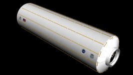
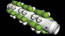
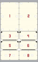
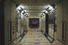
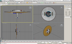
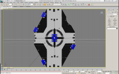
Some of you may recognize these. I've been working on them adding super detail.

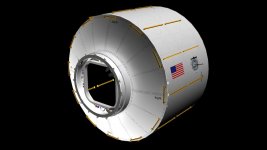
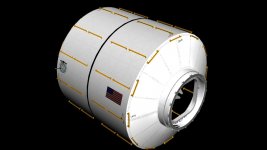
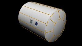
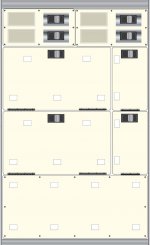
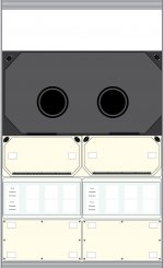
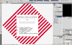
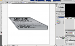
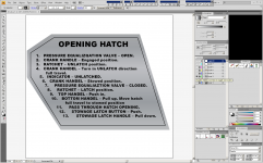
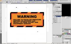
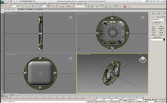
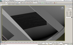
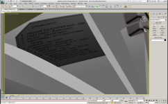
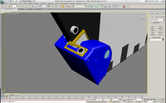
The CBM hatch is the most time consuming object that I've worked on yet. So far about 300 hours are in this thing. It's still not done. I've been learning new techniques of how to slice here, and section there. I learned how to make a flat decal and yet have dimension (all 3) to it. I made the two CBM instruction decals in Adobe Illustrator first. Once I licked it in 2D, I figured out how to make it in 3D. Then came the hard part, getting it to be contoured to look like an appliqué on the exterior of the hatch.

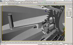
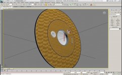
The dust caps, and air duct lids were also fun to make. I still have a long way to go on the plungers, but they are coming along nicely.

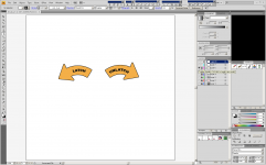
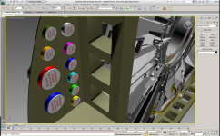
I discovered how to engrave text into an object, The latch indicators in different colors are an example. Getting them to curve was about 3 hours of learning.

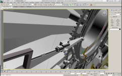
I learned how to "Pro Boolean" an object together, the Cam wheel is a great example of that effort, The Hatch bulkhead is another.

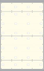
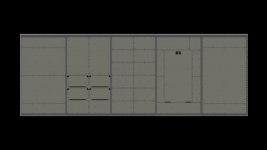
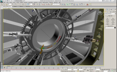
What you see here is mostly just raw color, and objects.

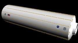
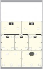
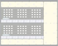
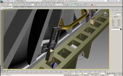
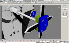
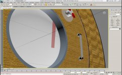
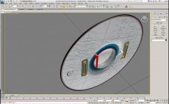
The LIDS hatch got a new window, thanks to a few Google searches, Its real, and it's transparent, yet has thickness, and shadow.

I improved the exterior grab iron, and made the hatch thickness the proper size. It turned out really nice. Of course these are now on version 51 of my CBM-LIDS adapter.

Although I have yet to use them, I figured out how to make Machine screws, and even though I know how too, I also found a nice repository of free fasteners on Google Sketchup Warehouse.

In order to save time, I'll be grabbing more items.

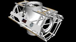
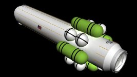
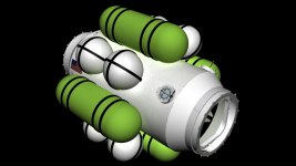
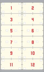
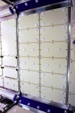
I had some fun and made the STORRM objects for my docking target, then I made the target board as well. Now it's complete, fully 3D and it looks fantastic.

Hope you enjoy this update, It's been a long time in the works, but well worth the wait.
 

Attachments

  • Image1.png
    Image1.png
    239.3 KB · Views: 35
  • Image2.png
    Image2.png
    479.4 KB · Views: 39
  • Image3.png
    Image3.png
    342.1 KB · Views: 26
  • Image4.png
    Image4.png
    444.2 KB · Views: 36
  • Image6.png
    Image6.png
    222.1 KB · Views: 20
  • Image5.png
    Image5.png
    273.2 KB · Views: 20
  • Image7.png
    Image7.png
    279.3 KB · Views: 22
  • Image8.png
    Image8.png
    339.7 KB · Views: 21
Last edited:
GWS Update Part 2

Part two
 

Attachments

  • Image9.png
    Image9.png
    384.6 KB · Views: 16
  • Image10.png
    Image10.png
    145.9 KB · Views: 15
  • Image12.png
    Image12.png
    233.7 KB · Views: 17
  • Image11.png
    Image11.png
    437.8 KB · Views: 29
  • Image13.png
    Image13.png
    154.7 KB · Views: 15
  • Image14.jpg
    Image14.jpg
    183.8 KB · Views: 17
  • Image15.jpg
    Image15.jpg
    179.3 KB · Views: 18
  • Image16.jpg
    Image16.jpg
    164.8 KB · Views: 19
Back
Top