- Joined
- May 18, 2008
- Messages
- 913
- Reaction score
- 0
- Points
- 16
- Location
- London
- Website
- wehaveaproblem.wordpress.com
This is an interesting project, and I'm sure its technically far more feasible than the 'near future' stuff I do. Kudos on the work. Anyhow...
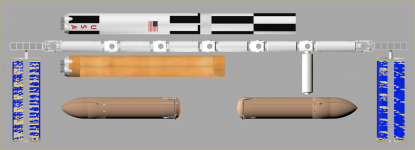
Although I like the look of the solar panels, and look forward to seeing their deployment an animation, but they strike me as being a bit inefficient wrt surface area and required structure to support them. That is to say, would a more classic long rectangle style panel design not give you more panel surface area for your money/weight?
Although I like the look of the solar panels, and look forward to seeing their deployment an animation, but they strike me as being a bit inefficient wrt surface area and required structure to support them. That is to say, would a more classic long rectangle style panel design not give you more panel surface area for your money/weight?