You are using an out of date browser. It may not display this or other websites correctly.
You should upgrade or use an alternative browser.
You should upgrade or use an alternative browser.
SSU Development thread (4.0 to 5.0) [DEVELOPMENT HALTED DUE TIME REQUIREMENTS!]
- Thread starter DaveS
- Start date
- Status
- Not open for further replies.

DaveS, the "swirling textures" are back in MOGE... :facepalm: It seems to be in the EDO pallet.
- Joined
- Feb 4, 2008
- Messages
- 9,753
- Reaction score
- 1,024
- Points
- 203
I'll take a look at it.DaveS, the "swirling textures" are back in MOGE... :facepalm: It seems to be in the EDO pallet.
---------- Post added at 08:45 PM ---------- Previous post was at 08:38 PM ----------
Looks fine here. I have checked in an updated version just in case.I'll take a look at it.
The more I look at panel R1, the more I think our diagram there is wrong: not only are the 3 "standard" tank sets switched with the "additional" tank sets, but there are 2 unlabeled "exits" in the H2 side which are similar to the ones on the O2 side (for ECLSS). I'm going to change it so it matches the SCOM panel diagram and all the photos I've seen, including this one from 1985:

(yes, I know it's a simulator but it still matches everything)
(yes, I know it's a simulator but it still matches everything)
What do you mean by "unlabeled exists"? Don't forget that the latest SCOM omits any mention of the EDO capabilities of 102/105.
"unlabeled exits" as in, we have 2 outlets on the H2 side, that I don't think exist in the real thing.
There is an older (incomplete) SCOM, from the late 90s I think, around in the internet, and there are no differences in panel R1, and it all matches Endeavour and the sim photo above from 1985.
- Joined
- Feb 4, 2008
- Messages
- 9,753
- Reaction score
- 1,024
- Points
- 203
Could you show me these outlets?"unlabeled exits" as in, we have 2 outlets on the H2 side, that I don't think exist in the real thing.
Could you show me these outlets?
They are in the diagram of our panel R1.
- Joined
- Feb 4, 2008
- Messages
- 9,753
- Reaction score
- 1,024
- Points
- 203
Now I see what you mean. They're not unlabeled and they do exist. They're just mislabeled like alot of stuff. The kit sections should be tanks 1 and 2 with 3 and 4 in the middle.They are in the diagram of our panel R1.
Now I see what you mean. They're not unlabeled and they do exist. They're just mislabeled like alot of stuff. The kit sections should be tanks 1 and 2 with 3 and 4 in the middle.
I've now corrected all that, and also the aspect ratio of the talkbacks which will be added tomorrow (a.k.a. later today... :zzz
") . I still have some work to do on the new mechanical meter vc components, but hopefully I'll commit the visible parts tomorrow and then I can start on the behind-the-scenes PRSD stuff.
. I still have some work to do on the new mechanical meter vc components, but hopefully I'll commit the visible parts tomorrow and then I can start on the behind-the-scenes PRSD stuff.- Joined
- Feb 6, 2008
- Messages
- 38,965
- Reaction score
- 3,937
- Points
- 203
- Location
- Wolfsburg
- Preferred Pronouns
- Sire
I've now corrected all that, and also the aspect ratio of the talkbacks which will be added tomorrow (a.k.a. later today... :zzz
Just started looking at the PSRD stuff in the Systems Handbook, looks like the mechanical meters are all driven by Display and C&W outputs of the Dedicated Signal Conditioners.
Also, the output voltage from the DSC is always 0 to 5VDC, so the "motion range" property of the mechanical meter should not be necessary. Also you could make input simply a public attribute - I used this pattern also quite often, the discrete input/output classes are made for it.
What do you think, do we need a DSC now? In this case, we should maybe also provide abstract base classes for the few sensor types (like temperature transducer, which gets converted by a "Converter, Resistance to DC" card (D) in the DSC) that the DSCs support. The exact measured range is defined by the sensor used, so the display has to fit to the sensor.
For selecting which tank gets displayed, I think a refactoring of the rotary switch class could make sense: Splitting front-end/handle (The VC component) from the back-end (the rotary switch itself) and allow chaining multiple rotary switches on the axis of a single handle.
I'm starting to "cram" for the PRSD today. :lol:Just started looking at the PSRD stuff in the Systems Handbook, looks like the mechanical meters are all driven by Display and C&W outputs of the Dedicated Signal Conditioners.
Also, the output voltage from the DSC is always 0 to 5VDC, so the "motion range" property of the mechanical meter should not be necessary. Also you could make input simply a public attribute - I used this pattern also quite often, the discrete input/output classes are made for it.
The "motion_range" member is needed so we now how much to animate the needle: x degrees, or y meters.
I made a Sensor class sometime back, which doesn't do much except convert the input value in the assigned range to 0-5v and put that in the discrete line. Maybe with some changes (a range from 3-5v maybe, or custom) that could feed the DSC?What do you think, do we need a DSC now? In this case, we should maybe also provide abstract base classes for the few sensor types (like temperature transducer, which gets converted by a "Converter, Resistance to DC" card (D) in the DSC) that the DSCs support. The exact measured range is defined by the sensor used, so the display has to fit to the sensor.
I think we need to have something like one VC component and then inside it "sets" of one output and several inputs to feed the output. It would clean up the panel code a bit, as that sequence of branches to plug one input line to the output line would be "hidden".For selecting which tank gets displayed, I think a refactoring of the rotary switch class could make sense: Splitting front-end/handle (The VC component) from the back-end (the rotary switch itself) and allow chaining multiple rotary switches on the axis of a single handle.
It could also be a good idea to have something like this for the "regular" switches, as they can have several contacts for different circuits.
- Joined
- Feb 6, 2008
- Messages
- 38,965
- Reaction score
- 3,937
- Points
- 203
- Location
- Wolfsburg
- Preferred Pronouns
- Sire
I'm starting to "cram" for the PRSD today. :lol:
The "motion_range" member is needed so we now how much to animate the needle: x degrees, or y meters.
Oh OK, you mean for the animation definition. I had not yet seen this in code, that made me a bit confused.
I think we need to have something like one VC component and then inside it "sets" of one output and several inputs to feed the output. It would clean up the panel code a bit, as that sequence of branches to plug one input line to the output line would be "hidden".
It could also be a good idea to have something like this for the "regular" switches, as they can have several contacts for different circuits.
Yeah, I think I only made a rotary switch for the multiple inputs to one output case, but not for the opposite (multiple outputs for one input)
That is why I think a chained solution could be nice there, because we could move multiple internal "switches" with one VC element.
For the regular switches, I only regret that they have just one contact there... actually each switch has three internal switches, for redundancy. But I still think this would be a too fine simulation of failures...
I still have the HAINS IMU here as primary task for me for the next time, but for that, I also have a few side tasks to do anyway.
- Inertial provider class (Helper for getting acceleration data for the various sensors)
- Serial I/O interface for MDMs
- IO API for GPC software
- Find information how IMU skewing was done on the Shuttle.
Yeah, I think I only made a rotary switch for the multiple inputs to one output case, but not for the opposite (multiple outputs for one input)
That is why I think a chained solution could be nice there, because we could move multiple internal "switches" with one VC element.
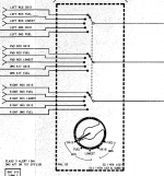
I don't think we need "multiple outputs for one input" (which it seems is what we have), but several instances of "multiple inputs for one output". I think this diagram shows what we need, as a switch controls 3 sets of 5-to-1 signal switches.
Attachments
- Joined
- Feb 6, 2008
- Messages
- 38,965
- Reaction score
- 3,937
- Points
- 203
- Location
- Wolfsburg
- Preferred Pronouns
- Sire
I don't think we need "multiple outputs for one input" (which it seems is what we have), but several instances of "multiple inputs for one output". I think this diagram shows what we need, as a switch controls 3 sets of 5-to-1 signal switches.
No, you invert the drawing there. The arrow in a rotary switch symbol does not point into the direction of information flow, it is just a connection, physically it is even bidirectional. The > on the left edge show the flow of information, these are inputs.
There you have many examples of multiple inputs to one output on one common axis.
I'm not saying it does. I'm just saying we need to have "several inputs and one output", several times (3 in the diagram). A quick look at what we have in the code tells me that we have one input and several outputs.
asdad
Womens From Your City - No Verify - Anonymous Sex
- Joined
- Feb 25, 2015
- Messages
- 138
- Reaction score
- 2
- Points
- 18
- Location
- USA
- Website
- privateladyescorts.com
GLS, I see in video STS-1 launch is not match in STS-1 scenario can you fix it ?
GLS, I see in video STS-1 launch is not match in STS-1 scenario can you fix it ?
Can you say what doesn't match?
- Joined
- Oct 26, 2011
- Messages
- 1,264
- Reaction score
- 727
- Points
- 128
I've recently begun developing rendezvous calculations for the Skylab rendezvous profile for NASSP, based on guidance equations of the Apollo Guidance Computer software version flown on these missions. The Skylab rendezvous profile includes two height adjustment maneuvers that set up the Terminal Phase Initiation (TPI) maneuver to happen at a specific time, e.g. orbital midnight, which is similar to the TI maneuver of the Shuttle, which is supposed to happen at 36 minutes before sunset. This Skylab rendezvous profile still uses coelliptic orbits, but the height adjustment maneuvers are very similar to the Space Shuttle stable orbit rendezvous.
A long while ago I already posted in the SSU subforum that I would be interested in developing some of these calculations for the maneuvers that set up the Shuttle rendezvous phase (NC, NH etc.). That is still the case and now I have started to get a grasp how that could be accomplished. But before I even start working on anything that would be Shuttle or SSU specific, I would like to get your feedback about how that would work the best for you.
I know how to develop an MFD, I've put all my calculations for NASSP in one. Is a seperate MFD useful for SSU? A "Shuttle MCC-H MFD" or something like that? Or should it be more integrated into SSU, maybe into an MFD that already exists? I only know how to do it in C++ though, so using your SSU Workbench isn't really an option. There are many functions I have already developed that I would be reusing, too.
Should it be SSU specific or also work with e.g. the Shuttle Fleet? If it works with more than SSU, then of course it can't be fully integrated into SSU. And the specific constraints (lighting conditions for RPM etc.) might be more relevant to a project like SSU. I guess setting up the Shuttle for the onboard targeted rendezvous phase can already be accomplished with more traditional Orbiter tools, just not for the specific constraints of the post-STS-107 ORBT profile with RPM and not with the small number of maneuvers and small required Delta V of realistic Shuttle operations. Of course you SSU developers could say "what do we care about other addons?", but I still wanted to ask your opinion about this. :lol:
A future expansion of my work could be deorbit targeting, Maneuver PADs etc., so stuff that I have already developed for NASSP. But that is far down the road for the Shuttle.
- Joined
- Feb 6, 2008
- Messages
- 38,965
- Reaction score
- 3,937
- Points
- 203
- Location
- Wolfsburg
- Preferred Pronouns
- Sire
Well, the workbench should be mostly for mission planning and scenario creation, any runtime capability should be purely diagnostic right now. (Maybe later we will allow multiplayer by letting somebody be MCC-H)
A MFD would be one option there, but I would prefer using a more integrated solution there, having a MCC building-vessel that can read the mission files as well, has its own knowledge of the mission state and communicates with the player via message lines on the screen and executive packages. In C++ of course. The MFD would break immersion a bit there, and would have some UI limitations. Having a dedicated MCC vessel would allow using a bigger UI and allow more functions. For example, using the sleep phase in a flight plan for preparing the next flight day manually (instead of making too much automatic)
A MFD would be one option there, but I would prefer using a more integrated solution there, having a MCC building-vessel that can read the mission files as well, has its own knowledge of the mission state and communicates with the player via message lines on the screen and executive packages. In C++ of course. The MFD would break immersion a bit there, and would have some UI limitations. Having a dedicated MCC vessel would allow using a bigger UI and allow more functions. For example, using the sleep phase in a flight plan for preparing the next flight day manually (instead of making too much automatic)
Last edited:
- Status
- Not open for further replies.
Similar threads
- Replies
- 12
- Views
- 3K
- Replies
- 137
- Views
- 22K
- Replies
- 143
- Views
- 34K
- Replies
- 21
- Views
- 18K