Project H-10-K Enterprises Gateway Station

GWS Update Part 3

Part Three

I think this view with a few objects removed makes the hatch look alot like a UFO, Don't you agree?:lol:
 

Attachments

  • Image17.png
    Image17.png
    118.7 KB · Views: 41
Damn, I can't believe you're still going at this one.
 
GWS Update

Interior Hatch (Smooth Side)

There are two different pressure valve assy. I took what looks to be the newer version. I looks huge but it's the right scale.

The latching mechanism was a pain to make, but it came out nice.

The inset cutout for the latching handel will not look prototypical, but hey, whos to say this isn't an inprovment over the ISS model.

The hatch plate is a flatter model than the ISS hatch.
 

Attachments

  • Hatch Interior.png
    Hatch Interior.png
    294.4 KB · Views: 35
GWS Update

It's still not finished, there are a few misc things missing, like a bolt or tw, some alignment arrows at the edge of the hatch, text on the pressure valve on the interior, and the equalization button-valve, a couple of lanyards.

Things I did do are the latch plungers, the slide mounts for the plungers that keep the end near the cam in place, the warning stickers, the track bearings, the cable clamps for the hatch lock, the handle/strap at the top, and the text for the cam wouldn't render so figured that out.

These are renders that show chrome pins, cast aluminum, fasteners by plated color, and so on. Enjoy, comments welcome, don't be shy.
 

Attachments

  • 001_Hatch Inner.jpg
    001_Hatch Inner.jpg
    54.1 KB · Views: 29
  • 002_Hatch Inner.jpg
    002_Hatch Inner.jpg
    82.6 KB · Views: 27
  • 003_Hatch Inner.jpg
    003_Hatch Inner.jpg
    49.8 KB · Views: 23
  • 004_Hatch Inner.jpg
    004_Hatch Inner.jpg
    41.6 KB · Views: 24
  • Hatch Plunger_10_20_2012.jpg
    Hatch Plunger_10_20_2012.jpg
    95.5 KB · Views: 28
Last edited:
GWS Update

Got the radiator fins tubes made. For some reason the first three radiator cones dont render, gotta work on that!
 

Attachments

  • Radiator Fins.jpg
    Radiator Fins.jpg
    323 KB · Views: 34
  • Radiator Fins a.png
    Radiator Fins a.png
    449.8 KB · Views: 37
GWS Update

Latching End Effector, efforts to refine the details. Minus the camera, but I've got some great close-ups, so It'll be along shortly.
 

Attachments

  • LEE-P-001.jpg
    LEE-P-001.jpg
    88.2 KB · Views: 44
  • LEE-O-001.png
    LEE-O-001.png
    322.1 KB · Views: 38
Been working on the database of objects. I also recalculated the power consumption of the station. "I missed it by that much" Power consumption demands dispite the improvments in efficiency of solar arays (now at over 44% vs 14% of the ISS SAs) still shows 16 panels only generating about 92% of the needed power. I had to add two additional panels outside the original 4 on each quadrant. This modification also drove the upgrade of the battery module to a modular system, What was once only one module at about 65' long is now Three modules each at 45-49' long. The two external modules hold 5 battery bays and are called intermediate battery modules. The interior module is 49' long to accomodate the SARJ or Alpha gimbal. It holds 5 battery bays as well. All the battery bays are packed with ORUs.

We now have 12 Beta gimbals to complete the sun tracking capability.

In addition in order to keep the reach of the RMS systems able to place the intermediate battery modules, all four trusses needed to be lengthend by two 70' segments. Adding an additional 140' to the overall length. Now each truss is 13 segemnts long instead of only 11. 910' long or Three Football Fields Floating Freely in Face, uh I mean space. Images to follow...

I modified the End caps of the trusses to have only 6 grapple fixtures, 4 PDGF, 1 DGF, 1 vanilla GF. Both of the LEEs are still there. This was driven by the presence of only one Robonaut 2, parked on each of the 4 Fwd endcaps. The external Robonaut 2s will have a LEE equipped with a PDGF oppisite of it's camera mount. This is so a Canada arm can grab it, delatch him from the parking spot, and then use him normaly at the end of the arm. It looks strange but it's practical and necessary.

There were a great many other discoveries as I did the research, some administrative, others altered both operations and configureation. My original Flight plan had to be scrapped and the sequince changed so much it was a waste of time to try and salvage it.

The trudgery goes on.
 
Last edited:
GWS Update (images)

Robonaut 2 with the LEE and PDGF modifications
Battery Modules as modified
The full array quadrant
Node CBM coordinat selection sheet.
Truss End Cap sheet after update of the End Cap. 6 parking spots now.
Top View Coordinate selection sheet.

I use this sheet and several others to select the coordinates of an object on the station. This is important only when on an EVA, and your not near the ID plate of a given object.
 

Attachments

  • Image10.png
    Image10.png
    180 KB · Views: 28
  • Image9.png
    Image9.png
    355.5 KB · Views: 22
  • Image7.png
    Image7.png
    79.6 KB · Views: 20
  • Image8.png
    Image8.png
    180.2 KB · Views: 23
  • Image6.png
    Image6.png
    149.4 KB · Views: 22
  • Image1.png
    Image1.png
    40.7 KB · Views: 16
I'm thinking of replacing my fixed length RMS segments with telescopic segments.

The idea is to create a small shipping configuration so a 100 foot long arm would colapse into a deployable package that would fit into the trunk of a Dragon spacecraft.

The arm would be much like the Canada Arm 2 aboard the ISS, except that the tubes that are fixed length segments, would be telescopic.

Each segment would be extendable only once, and would be deployed upon reaching orbit. At each end would be the Powered and Data enabled Latching End Effector

Not much info on this idea exists, I know only of a study paper done by NASA in 1977, and the Russian STRELLA system, except that STRELLA can be retracted.

Any thoughts on this subject would be appreciated, and additional research material would be very helpful.

TIA

I dont know, It sounds like the final product would be pretty flimsy/unwieldy, although it would be kinda funny having a robotic arm twisted all around the station like a vine.

Out of curiosity, what purpose is there to placing a station in GEO?
 
I dont know, It sounds like the final product would be pretty flimsy/unwieldy, although it would be kinda funny having a robotic arm twisted all around the station like a vine.

Out of curiosity, what purpose is there to placing a station in GEO?

Thanks for the input and question, I was beginning to wonder if anyone bothered to read the thread...

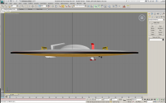
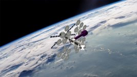
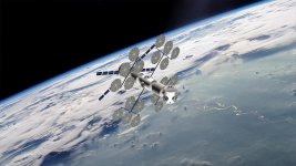
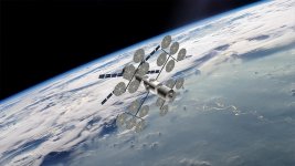
The 100' arm has 9 rotary joints. However unless special circumstances were needed only three of them are enabled at any given time. YOur right it would be interesting to see it twisted around the station modules like a peppermint stripe.

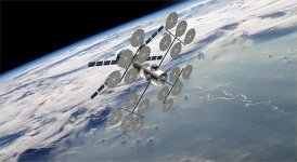
Placing the station in GEO does a couple of things.

The station would get sunlight in varing degrees through about 14 hours of the day, making the heat soak and cold soak in a contigous period instead of six to seven times a day. Stress cycles would be fewer, although they would be deeper. If you have a daylight time longer than the standard shift, then you have a longer window with which to EVA. Segway to EVAs...

EVAs would be commonplace on GWS, two of the large tanks are used to maintain satelites in orbit around earth in any altitude, LEO, Polar, Mid, and additionaly other GEOs. You would have the time to go get, and place these objects in a bay durring the daylight hours, which makes the manuvers a bit easier. The Darkside of the station hours could be placed on the start of an orbit, or the end of an orbit of an object that is out of phase with the station. Yes this is a shorter window, but still longer than a LEO orbit.

The station would be completely out of the shelter of the earths magnetic field, making direct observation of radiation exposure for everything from astronauts to new equipment and old equipment possible on a 24 hour cycle. The station would only pass through a week field while in the dark, and only durring the normal sleep cycle of 2/3 of the crew.

Additionaly it would be a better launching orbit for deep space missions. GWSs last feature is to be a construction platform for Mars missions and eventually other deep space mission.

But probably the best reason is that it has never been done before. NASA(USA) and the other cooperating countries would be intrigued at the least. Or this could be the most disasterous experiment of all. I'm not a PHD so I don't really know.

Great question, Thanks again.
 
I thought about sending up the parts of the arm unattached to each other, and join them in space like the [ame="http://en.wikipedia.org/wiki/Experimental_Assembly_of_Structures_in_EVA_and_Assembly_Concept_for_Construction_of_Erectable_Space_Structures"]EASE/ACCESS[/ame] experiments. Sections could be sized to fit inside the trunk of a Dragon, you wouldn't have to deal with the electronics(cable/wiring) moving inside the arm as telescopes out, and it could be extended/shortened later by swapping out sections. You could have the joints be on their own section, maybe allowing for orbital replacement of only the troublemaker joint section, with the simpler length sections and functioning joint sections being unaffected. A large 9 joint arm could with a spare end effector be split in two smaller 3 joint arms, or two 6 joint arms be joined in a 12 joint monster arm.

Bad things though: It would mean maintenance problems like replacing a bad section requires astronauts to go out suited up. Furthermore, the Next-Generation Canadarm has retractable telescopic booms, meaning designing telescoping arms might be easier than designing a new section-based arm system. And I thought I had something going there as a alternative system.
 
Bad things though: It would mean maintenance problems like replacing a bad section requires astronauts to go out suited up. Furthermore, the Next-Generation Canadarm has retractable telescopic booms, meaning designing telescoping arms might be easier than designing a new section-based arm system. And I thought I had something going there as a alternative system.

I've spent alot of time thinking about this issue, and it's neat the CSA has also been thinking about it. The telescopic boom section appears to be the right move.

On the maintenance end, If the maintenance bays are operational when a boom section or joint goes bad. The only thing need be done is bring it into a bay, presurize and heat, and bazinga you have a shirt sleve environment to work on the arm. at least that how I envision it to work. The maintenance bay of GWS are a handy thing to have. Too bad the earliest I can get one up is about two years into the assembly phase of the station.

Thanks for the input... The link is great, I don't think I would have deliberatly gone to it, did you find it in a search engine? What keywords?
 
While looking at the Canadarm page at Wikipedia, I figured the CSA website might have better info. I'm sorry I can't be of more help here. Maybe an email to the CSA asking for some info might get you something more. I'll try searching the web and the NTRS for something more later.

About sectional arms, hopefully they wouldn't need too much servicing anyway; hopefully being similar enough to the existing Canadarms to be as reliable. I think that without a dedicated effort by the designers and in the manufacturing process to be as reliable, sectional arms could be trouble-prone messes compared to a telescoping Canadarm. It could be very easy to build into the system a maintenance schedule that demands 'too much' EVA time. One of the Space Station Freedom designs got the axe for having too many EVA hours needed to construct it, and one of the benefits of a robotic arm is to reduce the need to sortie astronauts. A sectional arm could could add enough EVA hours to mess with the station's utilization or outweigh the benefits of the sectional design. Then again, from what little I know of Gateway Station, EVA hours could be less of a problem there than on a ISS-like station.

I'm finding sectional arms to be an interesting subject, and I hope I'm not going too far off topic with it. So I'll understand if you'd like me to maybe split this discussion off to another thread.
 
... Then again, from what little I know of Gateway Station, EVA hours could be less of a problem there than on a ISS-like station.

I'm finding sectional arms to be an interesting subject, and I hope I'm not going too far off topic with it. So I'll understand if you'd like me to maybe split this discussion off to another thread.

No trouble, all discussion is welcome.

About GWS, just scroll through this thread, and you should get the general idea. It's a ISS redeux, with a budget and more than 3 purposes.

Thanks
 
Been working on my launch schedule in MS Project 2012. I've come to the conclusion that this will be several .mpp files, one for each year of GWS, so fifty or so files in all. I should be able to summerize the 50 years into one file, and maybe summerize the resup mission, manned missions, and assembly missions.

Meanwhile I wipped up an integrated truss carrier WAG. It will carry 6 intermediate trusses in a 5 meter dia fairing. ACBM is for size comparrison and possible berthing while an EVA/robotic operation detaches and installs the trusses.

Assembly-01, and -02 missions depicted here.
ATV Propulsion stage sections are highly modified versions of WellandNoMatter ATV. Don't worry I'm remodeling the section and it's nearly done, but I still need to make textures. This prop stage is a place holder for now. The cupola is off the NASA high res ISS model, free for use, and I am.

The circular solar arrays are mine in case you wonder. I scratch made them in Adobe Illustrator, then exported the texture. The source file was huge, and the 3DS version was also huge, so I made a gengon and painted the texture on, much much fewer vertex and much smaller 3DS file resulted in a great array.

Comments welcome
 

Attachments

  • Integrated Truss Carrier.png
    Integrated Truss Carrier.png
    422.5 KB · Views: 55
  • Assembly-01.jpg
    Assembly-01.jpg
    160.6 KB · Views: 58
  • Assembly-02.jpg
    Assembly-02.jpg
    174.1 KB · Views: 68
Last edited:
About the telescoping arms discussion, I found this before I got sidetracked. It a patent from 1985 that while mostly about robotic grabbers does include a bit about a telescoping arm.

If you don't mind the question, how do the circular arrays in the third picture unstow themselves?
 
If you don't mind the question, how do the circular arrays in the third picture unstow themselves?

The leaves(Circular) were derived from the CEV concept. These fold in an acordian style, Theres an animation somewhere...

The branches (I call one assembly a "tree") will most likely be spring actuated and folded onto the trunk. Exactly how I've yet to develope. This Tree will fold down alongside the Node into a stowed position between the radial CBMs.

The system will be deployed, probably accompanied with an EVA. The system needed to be this big to provide voltage and current for the entire HAB portion of the station. It will be constructed first since it has all the accessories for permanent occupation. Latrine, Kitchen, Bunks, Storage, Gas Storage, Fuel Storage and so on...

Edit: The NASA PDF was a different concept than I'm used to seeing. It has made for interesting reading. Thanks.
 
Last edited:
GWS Update

Managed to orbit some more modules
Assembly 3 = Graviton
Assembly 4 = Node
Assembly 5,6,7,8 = Ladders

With the high res modules it's getting a lower frame rate, but still managable. These screen shots were from 3DS Max, and it's getting real tough to manage the modules, hince the extreme low-res ladders.
 

Attachments

  • Assembly-05.jpg
    Assembly-05.jpg
    205.1 KB · Views: 39
  • Assembly-04.jpg
    Assembly-04.jpg
    204.9 KB · Views: 41
  • Assembly-06.jpg
    Assembly-06.jpg
    204.3 KB · Views: 34
  • Assembly-07.jpg
    Assembly-07.jpg
    205.2 KB · Views: 31
  • Assembly-08.jpg
    Assembly-08.jpg
    204.5 KB · Views: 41
  • Assembly-03.jpg
    Assembly-03.jpg
    206.1 KB · Views: 44
Back
Top